
OnePlus 5 スクリーンとデジタイザアセンブリの交換

はじめに
手順 1 に進むこの修理ガイドを参照して、OnePlus 5のスクリーンとデジタイザアセンブリを交換しましょう。
この修理ガイドはあらかじめフレームに取り付けられたスクリーンを対象としたものです。
この手順では、バッテリーの交換を含む大幅な分解と、古いスクリーンから交換用スクリーンへの小さなパーツの移動が必要です。最も難しいのは、バックカバーのフレームクリップを外すことと、指紋スキャナーのケーブルを傷つけないことの2点です。
バッテリーが膨張している場合は、バッテリーが膨張している場合は、適切に処分をしてください。
安全のため、ラップトップを解体する前にバッテリー残量を25%以下に放電してください。これにより、修理中に誤ってバッテリーを損傷した場合、熱に伴う危険な事故の発生リスクを軽減することができます。
必要な工具と部品
修理キット
キットには、この修理ガイドを完了するために必要な全ての部品とツールが含まれています。


パーツ


ツール


もっと見る
-
-
SIMカード取り出しツール、ビット、またはまっすぐに伸ばしたクリップを、SIMカードトレイの下にある小さな穴に挿入します。
-
しっかりと押し込んでトレイを取り出します。
-
-
-
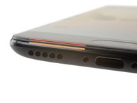
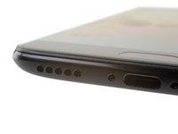
デバイス下端にあるUSB-Cポートの両側に留められた、2本の長さ2.6 mm T2ネジを外します。
What are the reference of the screws ? They are missing in the one I bought !
Hi Yôken,
They help hold the back cover on. Most of the time, the clips are enough to hold the phone together.
Just FYI, for whatever reason my brand new OnePlus 5 had 0,8 mm stars screws instead of T2 Torx.
strixaluco - 返信
Definitely T2 for me. Do watch out during assembly. I have a feeling that it’s easy to strip these.
T2 for me too. It was missing in my kit and iFixit sent it later when I asked them about it.
-
-
-
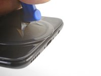
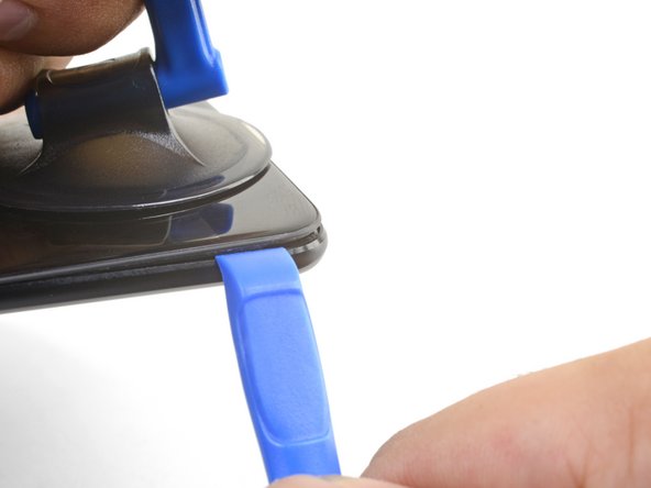
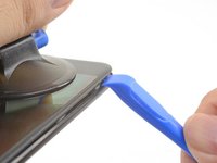
吸盤カップをディスプレイの下端付近に装着します。
-
安定した強い力で吸盤を上方に引っ張ります。
-
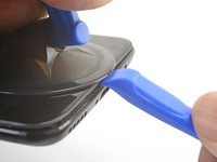
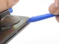
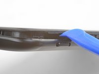
オープニングツールの先端を吸盤近くのフレームの継ぎ目にまっすぐ押し込み、エッジがプラスチックフレームとバックカバー先端の間に挟まるようにします。
I found the suction cup to be more of a hindrance and kept hitting the power button, making it necessary to stop and turn the phone off again. I watched a youtube video where the person didn't use a suction cup at all and decided to try that. I also found that a guitar pick type spudger worked far better than the one shown in the picture. If you're having trouble getting it started, I suggest trying those two things.
-
-
-
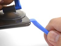
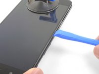
オープニングツールの端が所定の位置に固定されたら、ツールをデバイス下端に沿って慎重にスライドさせます。
-
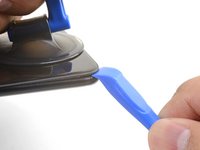
ツール先端端をデバイスの縫い目の内側に保ちながら、開口工具を携帯電話の左隅に注意深くスライドします。
This was extremely difficult & took a lot of force. I needed a thin flat metal spudger and wrecked a couple of plastic ones in the process. I left a few scratches along the join in the process. It would be easier if I had something to hold the phone, in my hand I kept turning it on by accident.
what was the metal spudger did you use? I am having trouble as well. I cannot seem to pry the back cover and it feels like it is shut tightly, there are no crevices I can pry into. What was your strategy may I ask?
At first, I slightly opened the body with a plastic tool, but it was not enough to actually open the back cover. Then I used a thin metal screwdriver for this. It was difficult but nothing special. Just be sure that you are opening the correct seam between the body and the screen and don’t make sudden moves. I bent nothing, everything came back in place when reassembled.
ivan -
Same as David here: the plastic opening tools/guitar picks were doing nothing (not even creating the first "crack") . In the end I managed to open it using Jimmy (the metal knife/spudger), but not without scratching the whole metal cover.
-
-
-
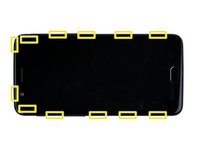
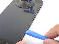
開口ツールを長辺に沿ってスライドさせ続け、途中でクリップを外します。
If you have difficulties with the last clip on the upper left. Try to go round the other side (right side), beginning at the bottom. This worked very well for me after having some difficulties with the clip near the front camera.
This helped me a lot as well. Couldn't get the upper left clip, but after going all the way around to the top right as well (keeping left clips released of course), it was pretty easy. Thanks, Sebastian!
-
-
-
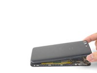
デバイス下端と左端が解放された状態で、フレームを軽く動かして上端と右端のクリップを外します。
-
フレームの上端をバックカバーに合わせ、上部のクリップが所定の位置にはまることを確認します。
-
デバイス長辺側に沿ってしっかりと握り、残りのクリップを所定の位置にはめ込みます。
Reinstalling the back cover stumped me for a second… If you’re struggling with aligning the top edge of the frame, remember that the camera is going to look off/pointed a bit too low until you actually clip the frame back in.
Really stupid but it was the only thing that tripped me up in this guide.
-
-
-
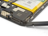
スパジャーの先でバックカバーフレックスケーブルをこじ り上げ、ソケットから外します。
If the flex cable pins are damaged, the flex cable can be replaced.
If the connecter pins (on the motherboard) are damaged, you might need to do microsoldering (or contact a microsoldering company) to replace the damaged connector.
Brendan -
-
-
-
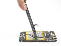
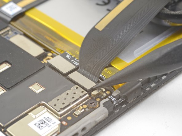
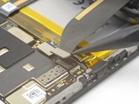
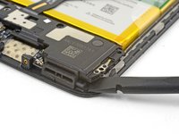
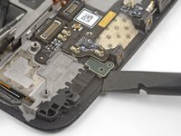
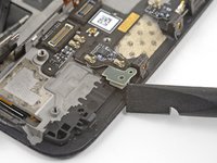
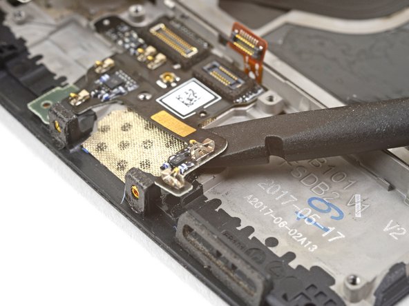
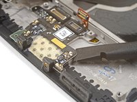
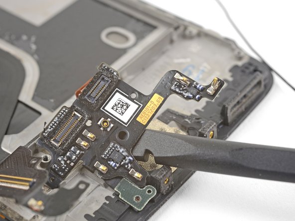
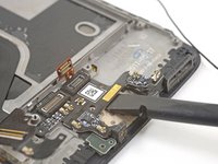
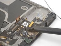
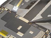
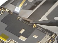
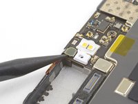
スパッジャー先端で相互接続フレックスケーブルをこじ上げ、ソケットから外します。
This step is used in multiple guides, and not all of them require the cable to be bent away. You can just leave it sitting there, disconnected.
This image seems to show the daughterboard removed but there is no corresponding previous step. I see no way to remove the interconnect flex cable without removing the daughterboard. Possibly the volume switch can be removed with the cable still connected but I'm not confident enough to try this so will remove the daughterboard.
David,
Thanks for bringing this up. That's indeed a procedural error! I've added the missing steps in the affected guides.
-
-
-
この手順で使用する道具:Electrical Tape in 6 Assorted Colors$9.99
-
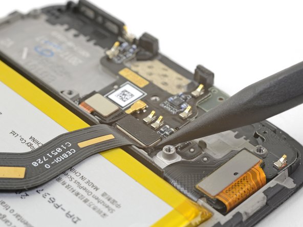
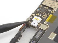
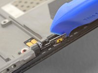
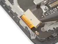
指紋スキャナーを覆っているテープの下にスパッジャーの平面側先端を滑らせます。
-
上にこじ開けて、テープを剥がします。
Hello! Does this silicone tape have the same thickness as the mesh that will be removed during disassembly? Do you have a mesh like that available or do you know a place to purchase it online?? Thanks
-
-
-
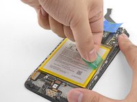
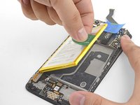
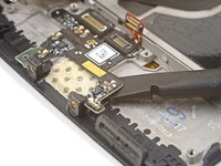
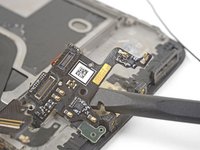
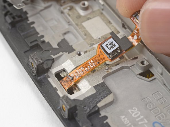
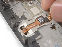
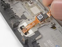
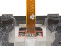
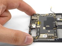
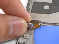
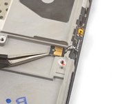
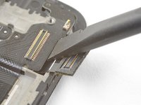
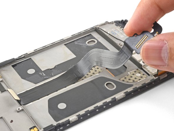
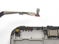
指で指紋スキャナのコネクタ端を軽く持ち上げます。ゆっくりと上に引き上げます。指紋スキャナーから直接引き離さないでください。
-
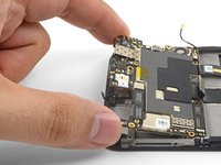
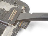
指紋スキャナケーブルが凹部から外れるまで、上方に引っ張り続けます。
I couldn’t release this by pulling upwards as shown. Maybe I wasn’t brave enough & could have pulled harder. I used a fine pointed end of a scalpel blade under the left side where the QR code is & that, while pulling gently, did the trick.
-
-
-
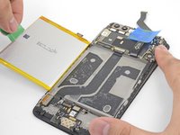
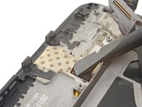
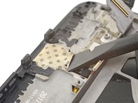
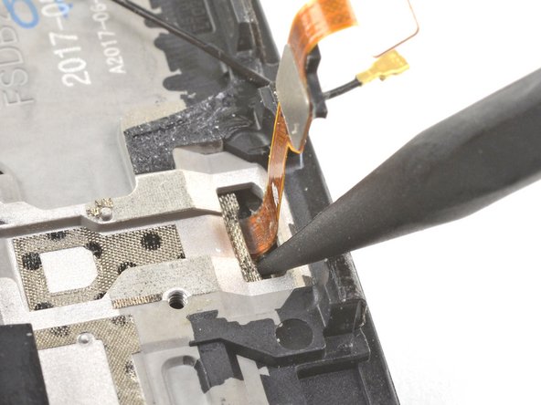
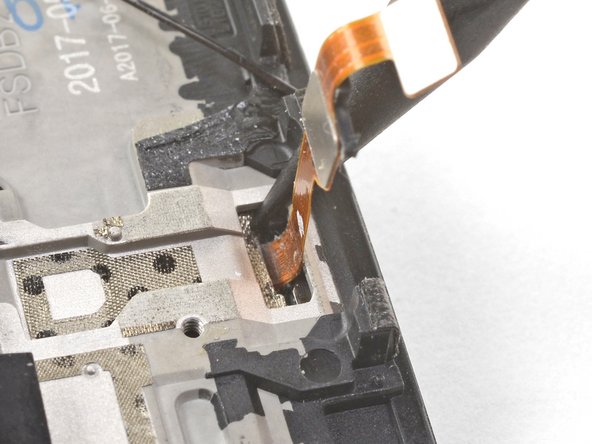
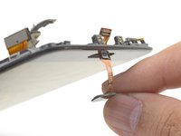
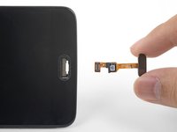
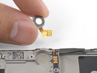
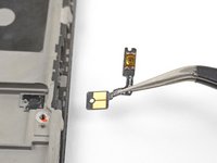
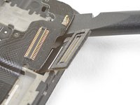
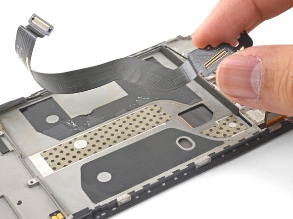
指紋スキャナーを凹みから緩めたら、フレックスケーブルを慎重に切り込みに通し、ディスプレイ前面から出します。
-
指紋スキャナーを外します。
My replacement fingerprint scanner did not come with any adhesive to hold it in place and it floated above the surface of the phone. I used a tiny amount of very carefully applied Gorilla contact adhesive which worked but will be a pain to remove next time.
-
-
-
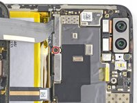
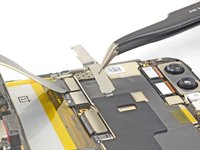
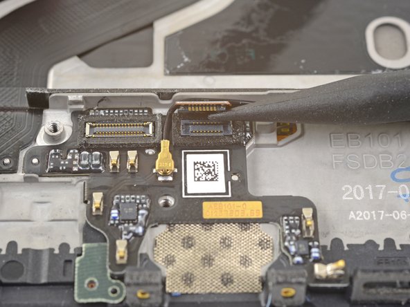
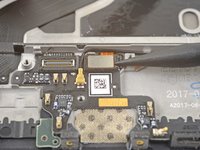
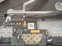
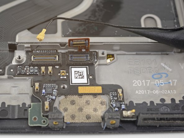
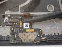
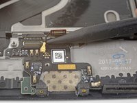
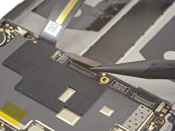
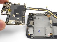
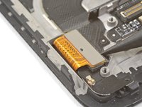
スパッジャーの先端を使って、マザーボードの底部端付近のソケットからディスプレイインターコネクトケーブルを持ち上げて、接続を外します。
Hallo, hier scheint der Schritt zu fehlen, in dem das Kameramodul entfernt wird.
Hello Norman,
You do not need to remove the camera module for procedure.
Hi Arthur,
You do need to remove the camera module, it’s in the photographs above, but not from step 33 onwards. It needs removing in order to remove the motherboard in steps 34 and 35.
Hi Alex! Thanks for the feedback! Can you relay which replacement guide you found the missing steps in? That would help me very much!
There are no steps 33, 34, 35 in this guide so the above comments must be from some other guide. With this phone I just lifted out the motherboard, carrying the camera with it. It went back the same way - but be careful not to trap the connector cable at the front under it.
-
-
-
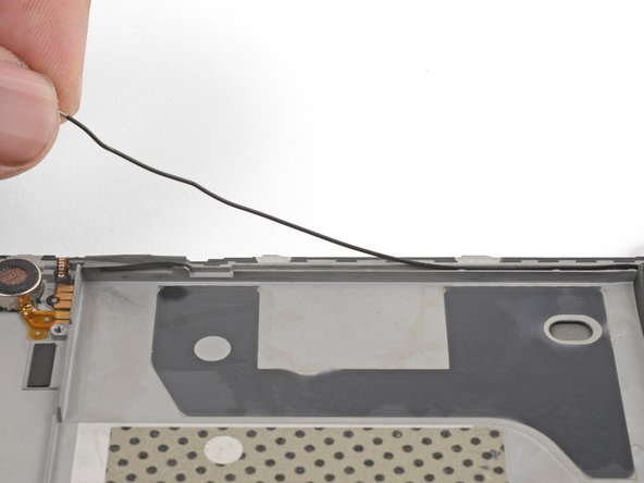
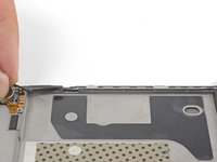
振動モーターの上のマザーボードに接続されているアンテナ相互接続ケーブルの下に、スパッジャーの先端を滑らせます。
-
こじ上げてケーブルをソケットから外します。
-
マザーボードのアースクリップからケーブルを外し、邪魔にならない場所に移動します。
Be attentive when reassembling if your unit doesn’t have a tape, which keeps antenna interconnect cable in place — I’ve accidentally got it squeezed with back cover.
strixaluco - 返信
-
-
-
マザーボードの上端近くに接続されている小さな四角いアンテナコネクターの下に、スパッジャーの先を滑らせます。
-
こじ上げて、アンテナコネクタをソケットから外します。
camera step seem to be missing
The cameras should be removed in step 14.
-
-
-
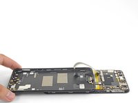
指を使って、マザーボードの上端を持ち上げます。
-
奥からマザーボードを持ち上げて外します。
The previous steps have not removed the camera although the pictures show it has been removed. I found that I could carefully lift away the motherboard with the camera attached.
When replacing the motherboard take care not to trap the small square antenna connector under the top edge.
-
-
-
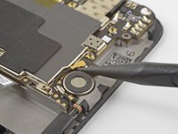
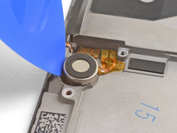
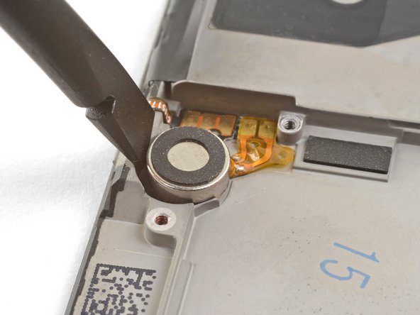
オープニングピックの先を振動モーターとフレームの間に挟み、下方向に押して振動モーターを凹みから緩めます。
-
振動モーターが少し緩んだら、スパッジャーの平面端をモーターとフレームの間に挟んで、モーターを凹みから解放します。
-
-
-
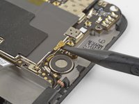
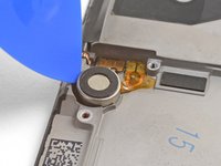
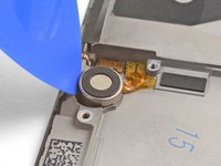
オープニングピックの先端を振動モーターのフレックスパッドの下に滑らせ、フレームから軽くこじ開けます。
-
振動モーターを外します。
-
-
この手順で使用する道具:Electrical Tape in 6 Assorted Colors$9.99
-
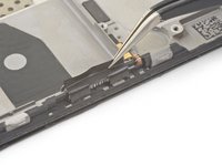
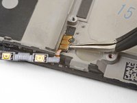
デバイス右端にある音量ボタンを覆っている黒いテープを、ピンセットまたはスパッジャーの先端でこじ開け、取り外します。
-
デバイス左端にある電源ボタンを覆っている黒いテープで、この手順を繰り返します。
-
-
この手順で使用する道具:Tesa 61395 Tape$5.99
-
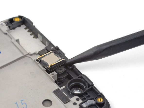
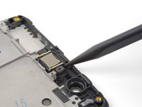
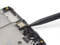
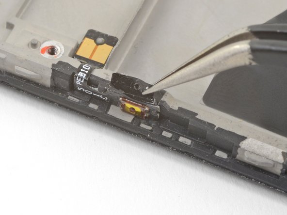
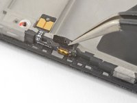
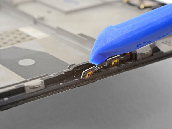
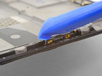
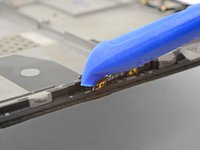
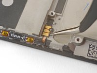
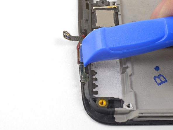
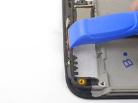
ピンセットの先端を合わせ、フレームの右上端にある音量ボタンボードのコンタクトパッドの下に差し込みます。
-
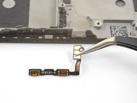
上方にこじ開けると、フレームからコンタクトパッドが緩みます。
-
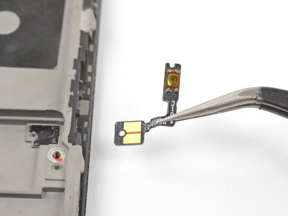
音量ボタンを外します。
Installing a vol button to a used frame I found the existing adhesive (a black sticky rubbery compound) still sticky enough to hold all in place except for the last 2mm of the outer strip with the switches which I fixed with a tiny piece of double sided tape. The tape was not at all adhesive & it's not obvious what it's for. Electric tape doesn't stick to the vol button strip so I used 2 or 3 pin prick size dots of contact adhesive to keep it in place. Fingers crossed!
-


デバイスを再組み立てするには、これらのインストラクションを逆の順番に従って作業を進めてください。
e-wasteを処理する場合は、認可済みリサイクルセンターR2を通じて廃棄してください。
修理がうまく進みませんか?ベーシックなトラブルシューティングを試してみるか、OnePlus 5のアンサーコミュニティを参照してください。
デバイスを再組み立てするには、これらのインストラクションを逆の順番に従って作業を進めてください。
e-wasteを処理する場合は、認可済みリサイクルセンターR2を通じて廃棄してください。
修理がうまく進みませんか?ベーシックなトラブルシューティングを試してみるか、OnePlus 5のアンサーコミュニティを参照してください。
33 の人々がこのガイドを完成させました。
以下の翻訳者の皆さんにお礼を申し上げます:
100%

Midori Doiさんは世界中で修理する私たちを助けてくれています! あなたも貢献してみませんか?
翻訳を始める ›


18 件のコメント
Nice. But where do you get the replacement part from?
Dear Christos, hope it is not too late, you can check Oneplus 5 screen replacement from Witrigs
HI . Do I need to buy an original screen and digitizer for my oneplus 5?
I'm from Argentina and on EBAY I do not see ORIGINAL parts
Can someone help me?
Hi Joselo,
You do not need an original, but that is probably the best quality. The original screen is AMOLED. There are also OLED and LCD replacement screens. These will not be as bright as the original AMOLED panel.
Hi, I need to know if this screen is like the original (Amoled) or not, and approximately how long it takes to send by mail to Miami Florida. Thank you OnePlus 5 Screen
Hi Joselo, that Screen and Digitizer Assembly is indeed an AMOLED screen and digitizer.
As for the shipping question: In order to determine shipping estimates, costs, and methods, you will need to enter your shipping address at checkout as this may vary based on the specific address.
If you ever have any questions, feel free to contact our iFixit Customer Support. We are always here to assist if you need anything. :)
Wow, this repair looks hard. I’d rather buy a new phone than attempt this.
Don’t blame you; the time commitment is hard to justify. However, I had a few hours to spare and took it slow: now I have a backup device from a (my first) phone repair :)
manual is very clear, successfully replaced the screen this weekend. difficulty is not too bad
Thanks for the guide, made me able to change my own screen for real cheap!
U forgot the front camera :)
Otherwise great guide!
The contacts for the vibration motor were hard to get off!
I left the front camera attached to the motherboard when I removed the board, but you can remove it separately.
The vibration contacts are pretty heavily glued in! They have to—otherwise, the motor will shake loose :)
Just used this guide, managed to get all the parts off my old phone but have noticed on the new frame there is not any black sticky for the parts to stick onto, it's just bare metal where they're supposed to adhere. Can anyone enlighten me?? Can I buy this double sided black tape? Is Tesa tape a good replacement? I'm assuming things will short out if I try to stick them into the bare metal frame?
Hi Rich,
Tesa tape is a good option! Depending on what you are sticking, you may only need the Tesa adhesive card. For smaller parts such as the side buttons, double-sided tape will suffice.
Nice tutorial. Everything works now after switching the screen. Took about 3h to someone with experience, but the steps are well documented.
The screen replacement from ifixit is not the same quality as the original (particularly the glass is very fragile); still, it's very nice to have access to spare parts and avoid buying a whole new phone!
Solid guide! Pretty intensive repair; only difficulty was to get a new piece of electrical tape to cover the buttons: ended up neglecting to replace that and just using them as is (with greater sensitivity).
my phone is lcd cant touch. what the problem? but lcd is some times on and off.