はじめに
このガイドを参照して、破損したNintendo Switchのスクリーンを交換します。この手順ではLCDパネルとデジタイザを一つのユニットとして交換します。デジタイザのみを交換する場合は、こちらの修理ガイドを参照してください。LCDパネルのみを交換する場合は、こちらの修理ガイドをご利用ください。
SwitchはJISネジを使用していますが、急なときはプラスドライバーでも対応できます。iFixitのプラスビットはJIS規格のネジと相互互換性があるように設計されているので、ネジを剥がさないように十分注意してください。
ご注意:シールドプレートを取り外す際には、プレートとヒートシンク間のサーマルコンパウンドを交換する必要があります。通常の放熱グリスは、大きな隙間を埋めるように設計されていないので、最も近い代替品はK5 Pro粘着性サーマルペーストです。ただしCPUには通常の放熱グリスが必要です。
ヒートシンクとゲームカードリーダーを取り外さずに、この修理を完了することはできますが、LCDパネルのリボンケーブルの取り外しと再接続がはるかに困難になります。この点に注意してください。
ご注意:この修理ガイドと弊社が販売するパーツは2017年に発売されたオリジナルのNintendo Switchモデルと互換性があります。モデル番号はHAC-001とHAC-001(-1)です。
必要な工具と部品
-
-
Joy Conコントローラーの裏面上の小さな丸いボタンを押します。
-
ボタンを押しながら、コントローラーを上側に向けてスライドします。
-
-
この手順で使用する道具:Magnetic Project Mat$19.95
-
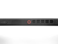
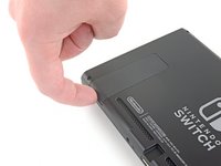
Y00 ドライバーを使って、リアパネルを固定している長さ6.3mmネジを4本外します。
I think my screws are stripped, any way to get them out?
I hear that using a rubber band can help? Not 100% sure on that though.
Pifase -
My top 2 screws are stripped, one into triangle, the other circle, rather than triangle spokes.
This happened when I replaced the micro-sd card slot, which turned out to have replaced the broken one with another one that turns out to be broken. I need to fix the fact that when I reapplied the back cover, the vent was misaligned.
I had huge problems removing the bottom two screws. I continued with the next steps and lifted the plastic shell as much as possible while using the screwdriver and it became an ease.
y0 works best. Press HARD at beginning then ease off to finish.
J LWsMommy - 返信
I haven't tried neither solutions that I am gonna propose here but
1. Poor some Isopropyl Alcohol, one small drop will do, get a piece of cotton (not any clothing) and dip it in the Isopropyl Alcohol, apply and then try to get a grip with tweezers and turn it out
OR (I do not reccomend it since it can cause huge damage if done wrong)
2. Grab a small drill and drill through the screw. Keep in mind; the screw is very small.
If you do one of these and it goes wrong, I am not responsible for that.
-
-
-
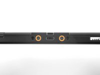
JIS000ドライバーを使って、リアパネルを固定している次のネジを外します。
-
デバイスの上部側面の長さ2.5 mmネジー1本
-
デバイス下部側面の長さ2.5 mmネジー2本
-
このような堅いネジが潰れないようにするためには、下向きにしっかりと力を入れ、ゆっくりと回してください。もしくは別のJIS 000またはPH 000ドライバを試してみてください。
Hey guys, I tried removing the upper screw and it won't go out(neither will it go in) any tips how to fix this?
Thanks
The screw boss might be stripped out. Has the device been taken apart before? If you can unscrew it a little bit to get the screw to peek out, maybe try and grab it with some pliers as a last-ditch effort.
I have the same problem. The JIS 000 tool works great on the joy con rails per step 5 but refuses to turn the bottom two 2.5 mm screws as in step 4. These bottom screws are noticeably smaller than the screws as in step 5. The JIS 000 does not get down into these screws. Hopefully they haven’t been stripped by the wrong tool. So is there a JIS tool that is smaller than 000? I’m stuck at this point…
We used the JIS 3.0mm screwdriver for both top and bottom screws and it worked
Fun fact: these screw into little plastic tabs that stick out of the rear panel. Apparently those tabs are fragile and easy to just break off…
If the screw is turning but not coming out, the plastic tab that it screws into is probably damaged or broken. You’ll need to try to pry the screw out with tweezers as you unscrew it. It is not the end of the world if you can’t screw these back in during reassembly.
this screws are way too fragile and way too small so be careful when taking them off dont use much force and unscrew also one of them fell somewhere and spent 30 mins searching for it
PH000 will work if you don’t have JIS000. The large IFIXIT kit has both and I lost JIS000. Just be very careful as you can strip the heads when removing or inserting easier.
One thing that worked pretty well for me with the screws not coming out is slightly prying on the back cover to put them under some tension
I just came here to also confirm and say thanks to Florian for the tip. This saved me a lot of time and frustration.
Quick note, these screws are not magnetic. A magnetic screwdriver will hold onto any of the others safely, but you need to be careful not to drop these ones in particular.
Jason Lane - 返信
These would just keep rotating and not come out. What worked was, as Florian Kraupa suggested, i slid a plastic pick just between the 2 shells near the screws to prise it open slightly, then unscrewed and out they came. They're the smallest screws I've ever almost not seen before, so be careful with them.
Der Tausch von Akku (separate Anleitung) und Lüfter ging einfach vonstatten. Die Anleitung ist echt gut und leicht verständlich. Man sollte aber gewohnt sein, mit extrem kleinen Anschlüssen, Schrauben und Platinen zu arbeiten, da alles da drin recht klein ausgelegt ist und keine Toleranz für grobschlächtiges Arbeiten erlaubt! Meine Switch ist nun wieder wie neu :) - Danke iFixit!
The swapping of battery (separate instruction) and fan was fairly manageable. The instructions are easy to understand. One should be used to handle with extremely finnicky connectors, screws and circuits as the components are really small and do not allow any tolerance for rough handling at all! My Switch is good as new again :) - Thank you iFixit!
My original switch bought on launch day does not have any of these screws. I'm guessing they fell out since the plastic tabs they attach to are broken. FYI, in case anyone else does not have these screws...
-
-
-
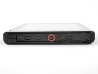
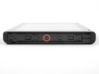
JIS 000ドライバーまたはiFixit公式のPH 000ドライバーを使用して、本体側面の3.8mmセンターネジ2本(左右各1本)を外します。
I tried my JIS 000 on Step 5 and was unable to get the screw to budge. It’s partner from the other side came right out with no trouble. Don’t really want to narf up the screw, so I bailed out. Anyone else have this issue?
Could just be torqued down a bit more! I’d recommend making sure the driver bit seats nicely into the screw, apply some downward pressure, and slowly twist to try and back it out. Good luck!
Yeah I’m having this exact issue. Screw stripped and now I’m stuck. Wish I hadn’t even started.
What worked for me here was a Phillips 000, not a JIS 000
My kit only has two screwdriver heads! The package was open when I received it!
I had this issue as well. Screw was irreparably stripped. If you can get every other screw out, just keep applying pressure with a flat head screw driver right above the stripped screw and try to break the plastic piece holding onto the screw. It's a very minor invisible bit of damage that will allow you to continue the repair.
after getting all the other screws off I just hinged the back part away and it snapped off neatly where the rusted screw is. not the best solution but it worked.
Steve T -
One of my screws was SUPER attached too, but after following a bit noticed the one other in the left that got out nicely, had the plastic tab broken already! So I went ahead and broke the other tab too. So the two side screws are now holding nothing. But I think it will work thanks to the other 4 or 5 screws. Too bad!
-
-
-
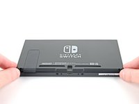
リアパネルをデバイス下部から持ち上げて、取り出します。
-
リアパネルを本体底面から持ち上げて、取り外します。
How to remove micro SD port?
Pull straight up, press back into place when closing back up.
This step is missing in this guide. Here are the steps from another guide:
Step 9) Nintendo Switch 右側ジョイコン センサーレールの交換
Step 10) Nintendo Switch 右側ジョイコン センサーレールの交換
When I lifted up the back cover, it kind of stuck near the headphone port (even with cartridge slot open). But it wasn't a screw or anything and I kind of carefully pulled and wiggled and the cover came off ok
+1, there is definitely an extra clip there on my day 1 switch
I wasn't so careful here and found out during reassembly that I accidentally broke off the clip with the screw hole on the top of the back cover (the clip fell off the device when I turned it over), so I can't put the top screw back in, but oh well at least the back cover is still affixed to the device otherwise
If you're having trouble getting the back cover to fit during reassembly, check to make sure you don't have an SD card inserted in the slot. It will get in the way.
If you're like me, you might have inserted the SD card to verify your SD reader was working again after doing step 9 reassembly. If so, remove it before proceeding.
-
-
-
JIS 000ドライバーもしくはiFixitドライバーPH000を使って、デバイス本体にmicro SDカードリーダーを固定している、長さ3.1mm プラスネジを1本外します。
-
-
この手順で使用する道具:Tweezers$4.99
-
指やピンセットを使って、microSDカードリーダーの接続を外してデバイスから取り出します。
Yes. The reverse is not so simple- you can’t see what you’re doing when you attempt to reconnect and it only takes one small error to completely bend the contacts on the connector. Very delicate.
if you very gently remove the foam pad sticker, you can at least see better how it lines up and can feel your way to a degree… then you can stick the pad back in. The pad seems pretty critical in keeping things in place once reassembled.
Definitely agree about not sticking the foam pad back on until the new SD card slot is connected. Saved a lot of headache. Great walkthrough and easy repair!
Tried several times to replace this SD reader module. As mentioned above, the issue is aligning the connectors together. It appears the foam tape is being used to hold the connection in place. (assuming you can make a viable connection) I am rather surprised at this design. In my experience, mylar ribbon cables like this usually slide into a small PC mounted socket. It appears Nintendo went the cheap route here. This design is prone to failure since it does not enable a positive connection - at least from what I can see.
I found it easier to connect it without the black foam pad so I could see and than add the foam pad over it. It was super easy and I an I 33 Mom doing this for my son. Was well worth the money for the kit saved us almost 100 bucks
Had my son follow this guide to fix his own switch where the ad card reader didn't work. And he did. Great instructions!!!! Thanks a million!
The only difficult part of following this guide is connecting the new sd card reader into the poorly designed motherboard connector. Its quite possible the sd card reader that came in the console wasnt broken at all.
The repair kit works just as advertised and even comes with stickers.
I’m still getting error 2002-2054 even after replacing memory card reader module. Thanks, Nintendo!
My switch won’t read my microSD card after I reassembled it (error 2016-0641) please help!
Tip: Keep the old SD reader piece loosely attached while you line up and gently press the new SD component into the connector on the motherboard. Once the new piece is snug, then carefully remove the old piece keeping the sticky foam in place.
I am a middle-aged mom with absolutely no special tech skills and I easily followed the directions and successfully fixed the broken SD drive. ifixit is the best!
Ah good! i have more confidence now in doing it once you said you're a middle age mom with no experience
I missed this bit about reconnecting the SD card reader under the foam pad and didn’t realise until my son pointed out a data storage problem?. All fixed in about 5 minutes taking advice from the replacing the SD card reader fix, especially removing the foam pad from the connector to better see and feel what you’re doing. All sorted!
Awesome guide! Very easy to do with the supplied kit
Tank you very much, and by tank I mean M1 Abrams, jokes apart easy and simple to follow
Thanks for the guide, I was struggling to find a solution, replaced more sd cards, before I stumbled upon this post. The Switch of my children works flawless again!
This helped me to reseat my SD card reader ribbon cable. I was getting the 2016-0641 error and no card work. A drop had dislodged the cable partially. And yes remove the foam pad gently to properly connect the cable. You can reuse the foam pad.
Kris Morey - 返信
For anyone who ends up bending the pins like I did while trying to reseat the microSD card reader…
I suggest gently placing very thin tweezers (like the curved ones in the Pro Tool Kit) in the gap and very, very gently pressing them back into alignment. Took a little effort but I was able to realign them enough to sit it in place and have it later working after reassembling the console.
When reassembling, note the alignment pins in the left and bottom notches before tightening the screw
Jason Lane - 返信
Super gemakkelijk te installeren met behulp van deze zeer duidelijke handleiding (met dank aan de vertalers!)
Wel even goed opletten op de aansluiting op het moederbord is zeer fragiel.
It is key to remember most out of the box issues with the SD card reader, do not require a replacement part and can be solved with disconnecting then re-connecting the reader at the motherboard.
Only when a simple re-seating at the connector doesn't work should you buy the replacement part.
I bought the kit and followed the directions. I plucked the black rubber foam off with a pair of eyelash tweezers. Putting the tiny screws back in place also was made easier using the tweezers. As for placing the SD card in place I think I got a bit lucky. I lined it up and gently pressed until it simply went into place. I do believe being gentle is the key there. But it went in and I put it back together. The deconstructing and reconstructing is what took the longest for me at least. I turned it on to verify it worked and then unpowered the unit and inserted the card. The system recognized and update right away and did it and then recognized the card! Just what I need for 20 something dollars. Son is happy and back to gaming.
Thank you for postingthis fix. The original sd card reader had come unplugged from the motherboard, so replacement reader will be a spare.
Anybody found a way to ensure the sd reader stays in place?
It was my first time repairing a Switch and the fan replacement wasn't too hard, but unfortunately I think there should be a better warning about the SD card connector because I damaged it while trying to put it back in. I couldn't hear any click and it didn't seem to stay put and I think I ended up applying to much force and damaging the pins.
Managed to push the connector back in with foam on, used back of plastic tool to push secure and once completed was able to use the SD port again. Brilliant little guide.
so how would you theroedictly put the old slot back on.
and how does if even work
Horrible guide, incomplete. Needs to show how to reattach the new reader but doesn't show anything. This makes it incredibly easy to bend pins that become incredibly difficult to fix. Ended up bending pins on the connector beyond repair as I didn't know what to look for or how to reattach it. Wouldn't recommend
Tried to do this, everything went smoothly I thought, but when I turn on system w SD card in the new slot, immediately freezes up the system completely until I hard shut down. Did I do something wrong?
Nate Akers - 返信
"Draw the rest of the !@#$ing owl"
Droideka30 - 返信
I have an issue that when I insert the SD card with the case off (to test the connection is correct), the switch reads it no problem. When I put the case back on, it no longer reads it. Anyone else experienced this?
This bullshit replacement part broke after two weeks of use, and now the connector on the board is damaged. My Switch is probably &&^&@@.
Thanks, iFixit! -
-
-
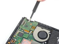
JIS 000ドライバーもしくはiFixitドライバーPH000を使って、デバイスにシールドプレートを固定している長さ3mmネジを6本外します。
Some models have a small board in the lower left beneath the kickstand which accepts SD cards. This will have to be carefully removed with its connections popped out, then replaced after.
Yeah, that “small board” is the microSD Card reader chip, which was covered literally one step ago. All models have a microSD Card reader, that’s how game data is stored…
nin10doh -
My switch had loctite (or similar) on the bottom right screw (farthest right), ended up striping it and having to use a Dremel to cut a slot in the screw to get it out. I've heard that heat (solder gun) can be used to loosen loctite, hindsight. Only screw I found with loctite.
-
-
この手順で使用する道具:Tweezers$4.99
-
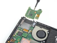
指先もしくはピンセットを使って、ファンの排気ポート付近のデバイス上部端のフォームを剥がします。
My Switch (bought about two weeks after launch) seems to be missing this foam piece… Was it added later, similar to the foam piece in the left joy-con (to improve connectivity)?
It’s possible it was added to newer units! Nintendo slightly updated the internals of the Switch not too long ago.
My launch Switch also does not have this piece of foam, so it was most likely added later.
Also did not see this in my launch switch.
Me three, no foam.
-
-
-
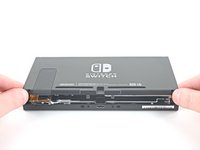
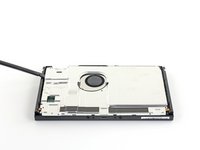
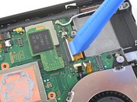
デバイスの端に沿ってシールドプレートの下にスパッジャーを挿入します。
-
こじ上げてシールドプレートを持ち上げ、デバイスから取り外します。
-
ピンクの放熱グリスは、注意すれば再利用できます。グリスを良い状態に保ち、再組み立ての際にヒートシンクとシールドの間にしっかりと接触すさせてください。
-
交換が必要な場合は、放熱グリスの塗布ガイドを参照して古いサーマルコンパウンドを取り除き、再組立時にK5 Proなどの適切なコンパウンドに交換します。
How do you know if the thermal paste needs to be replaced?
Youji Hong - 返信
Once you remove a heatsink you must always replace thermal paste even if you had just applied it ( or add a little more) . The reason is that once heat sink is fitted, paste splits around because of pressure and only needed amount will remain. If you remove the heatsink then some paste will move so when installed again there will be spots without paste. Hope this is clear enough. In any case cost of paste is very small compared to work time and value of your equipment…..
MacTek -
When your switch starts to lag and drop FPS, if you play breath of the wild and it starts to slow down in heavy areas like the forest where you get the master sword, can i use artic mx 4 insted of the pink compound?
Diego Soto - 返信
I’d like to know as well if a cpu thermal compound like arctic mx-4 can be used to replace the pink compound
No you shouldn't . It will spill around because it is not viscous enough and then there will be no heat transfer. As suggested by author K5 PRO is the most appropriate compound for such cases.
MacTek -
Arctic is generally only supposed to be used on bigger heat sinks like a personal computer. Its not nearly as thick or gummy compared to K5 PRO, and you should always use something that’s thicker for smaller project like a Switch/phone/tablet.
Why was this not included in the tools/equipment list? Getting to this step and now I will have to reverse and wait for yet another order to arrive. ? Very frustrated
Hi Amanda,
Thanks for bringing this up. Sorry! We inadvertently left that part out during the guide refresh. I’ll add the necessary info into the step.
I agree with Amanda, hopefully I don't lose any parts before I can get the paste. This seems like it should almost be included in this kit from what I've read about this repair. Mine certainly needs to be replaced. I feel like at the very least, this should be at the top of the guide and part order page in bold, red, all cap lettering.
Side note this is the only "issue" I've had of the 4 purchases I've made with ifixit. I recommend you guys every chance I get. I really enjoy doing these repairs with my son.
does ifixit not have an appropriate thermal paste for this step?
there is only arctic silver 5 in the kit and i would guess that that should not be used in this case.
if true, the kit is incompleteLucas Tigy - 返信
Since I couldn't find decently priced K5 I used a 0.5mm thick thermal pad and that seems to have done the trick quite well.
The Amazon link goes to a kit with 6 tubes of K5 Pro. Surely I don’t need 6 tubes… is this kit sufficient? https://a.co/d/5aU8kB7
When replacing the thermal paste, is it possible just to clean the old thermal off the back plate and top of the copper heatsink and just re-apply those areas only, without removing that copper heatsink?
Linn Mckay - 返信
-
-
-
-
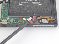
スパッジャーのポイントエンドを使って、バッテリーの接続を上向きに持ち上げて、マザーボードから外します。
be careful not to pry it off the board entirely
This was an old switch and the entire thing with the black plastic came off.. Most of the pins aren't there anymore, too.. is there a solution to that? Does soldering work?
it's probably possible, but unless you have experience with microsoldering, you'd probably be better off taking it to a local repair shop
You can use a spudger to hold down the black plastic side of this connector that is supposed to stay attached to the motherboard while using the pointy spudger as shown in order to reduce any chance of pulling the socket off the motherboard.
-
-
-
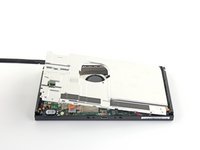
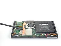
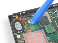
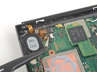
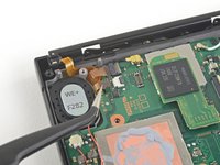
ヒートシンクとファンの両方に貼られた2枚のフォーム製スチロールを慎重に剥がしてください。
-
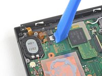
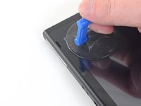
何も装着していないフォーム部分にスパジャーの先を差し込みます。
-
フォームの上部を指で押して固定します。
-
スパッジャーの先端をフォーム下の反対側先端までスライドします。
Maybe it’s because I’m working on a day one switch and the adhesive is just old and stubborn, but this didn’t work well for me. Am I just completely out of luck, or can I order a replacement for the foam?
Trae Block - 返信
I had the same problem and I found a foam manufacturer: https://www.foam-material.com/sample-cus...
I'm pretty sure the type is "Granular Activated Carbon Foam" and the thickness is 0.5 mm but I have no idea what the porosity is.
Yeah ripped the foam. Neither the screwdriver nor spudger technique worked. Day one switch, so 6 years old at this point.
Ndragonawa - 返信
Does the foam need replacing if torn? What does it actually do.
I wanted to know as well, what does it do? Can I replace it with thermal pads?
Can I replace the foam with a 0.5mm thermal pad? Will it be a better solution?
The adhesive remover really helped here being a day one switch
how do you re-glue the foam when putting this back together?
-
-
-
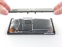
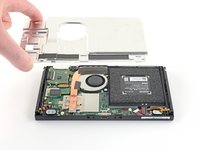
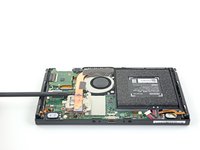
スパッジャーもしくは指先で、ヒートシンクを持ち上げて、マザーボードから外します。
-
以前にサーマルペーストが塗布されていた全ての表面に、サーマルペースト(放熱グリス)を塗布してください。これには、ヒートパイプとアルミシールドの間も含みます。
What's on the heatsink?
where do i get more of that black fabric like tape that is on the heat sink?
They may sell it in the ifixit store.
(1) Exactly how much thermal paste should be applied to the CPU?
(2) Which application method should be used? The linked instructions list four methods (vertical line, horizontal line, middle dot, or surface spread) but it’s not clear to me which one is appropriate for the Switch. Thanks!
UPDATE: So, for anyone who also wanted to know the answers to these questions:
1. I ended up eyeballing the amount. Imagine an amount the size of a pea, then split that amount in half. That’s how much I used, and it worked fine.
2. The paste (I used K5-Pro as recommended) is quite thick and sticky and difficult to get to behave the way you want, so I ended up just doing the “middle dot” method and spreading it a bit with a popsicle stick before smushing it the rest of the way down with the heat sink. Seems to have done the trick.
Good luck!
Travis -
you can also spread it with the spudger or any non-metalic tool if you are not sure how much you put
just clean it afterwards
K5 (or thermal pads) is ONLY needed between the copper pipe and metal shield plate. It is a pad replacement compound and is not meant for high heat applications like CPUs as it boils and creates air gaps. Air=bad for heat transfer.
Regular thermal compound/paste should be used on the CPU. You’ll have a sticky mess to clean but if you want proper cooling it needs to be done. The instructions clearly state that regular compound is used on the CPU.
Cerus98 -
i used artic silver 5 and worked just fine
The steps doesnt specify but do you have to remove the heat shield from the cpu as well?
-
-
-
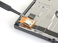
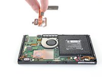
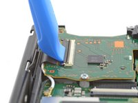
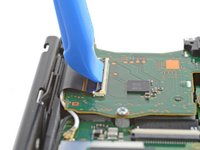
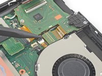
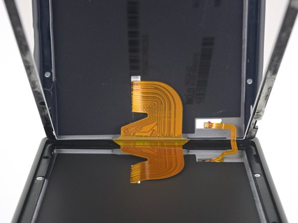
開口ツールもしくは爪先で、デジタイザケーブルのZIFコネクタ上のヒンジ状のロッキングフラップをまっすぐ上に持ち上げます。
This step broke my switch i can't use my card reader anymore! i tried numerous time the reverse it seems my headphone jack works but my touchscreen and gamecard reader is broken. Even worse one of the screws to attach this plate was mangled so i cant even replace it anymore because the screw wont come out anymore. I reallly hate that i followed this guide others suggested to just keep the gamecard touchscreen ribbon attached and just fold it like a book. I wished i did that. I not gonna bother to even buy an gamecard replacement anymore. Its time to buy an switch oled and be done with this!
The advice to "fold it like a book" will not work, as the cable will need to come out of the switch in order to replace the screen. It can not be kept in the slot.
To anyone reading this step: This is not an isolated incident. The loss of functionality of the game reader board, which includes the use of reading cartridges, the touchscreen, and the headphone jack, is an possibility that can happen if you disconnect the board. Unless you are replacing the board itself, do not do this step. As of 1/15/2023, there is no know reason why this happens or no known solution other than buying a new game reader board.
Update: If your Switch has lost the ability to read games and or the headphone jack in addition to touchscreen functionality, please consider reading this thread and its solution: Nintendo Switch Cartridge Reader Not Working After Fan Replacement
it is really hard to see what you need to flip up. look at it from different angles. it's the thinnest little strip of black plastic.
Please help I replace the game card read and head phone. Now my switch wont even turn on.
-
-
この手順で使用する道具:Tweezers$4.99
-
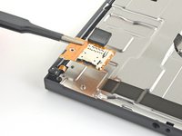
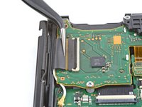
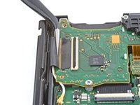
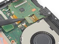
ピンセットを使って、ゲームカードリーダーのコネクタからデジタイザケーブルを水平にスライドして外します。
-
修理後、タッチスクリーンが動作せず、ゲームカードリーダーが動作する場合は、このケーブルが正しく挿入されているかどうか確認してください。ゲームカードリーダーも動作しない場合は、代わりに次のステップでゲームカードコネクタを確認してください。
The reverse of this is a little tricky - it may be helpful to post some more detail about getting the ribbon all the way back in and ensuring the clasp goes down to troubleshoot some of the touchscreen comments below.
This seems to be purely for the touchscreen to work, if you remove the headphone/card reader the switch will still function fine, however without somewhere for this cable to reattach your touchscreen will be disabled
Ian Wilson - 返信
the reverse of this is tricky. i'd suggest a better tool kit with this that includes real tweezers so i don't have to use my wife's
Did you get it to work finally?!
Hi Chris! From the thread, it looks like it's not this connector that's the problem, but the press connector in the step below. If your card reader won't read cards, check to make sure this connector is fully aligned and seated.
This connection was a problem for me. I tried the connection many times before it worked. What finally worked was lining up the gold rectangle on the back of the smaller part to overlap/cover the port very carefully. This required me to compress the ribbon a bit. Not much force required to finish the connection.
I found it much easier to reinsert the ribbon while the reader board was fully disconnected. This way I was able to simply hold the reader board with my fingers and slide it over the end of the ribbon while the ribbon was just sticking up in the air. The ribbon is quite stiff and slipped in VERY easily in such a way that I felt confident that it was fully seated. Then while holding it in one hand, I flipped the locking flap down with a spudger in the other. You might also be able to seat the board and the ribbon will likely stay inserted under its own tension, then flip the locking flap down.
-
-
-
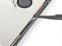
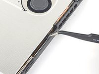
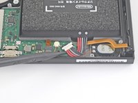
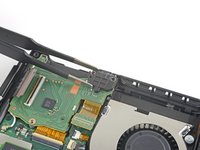
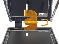
スパッジャーを使って、ヘッドホンジャックとゲームカードリーダーのコネクタを、マザーボードから持ち上げて接続を外します。
Note that if the card reader mentions it won't read cards, this cable has not been reconnected correctly. Watch the connectors are not bent when reattaching
You need to push the connector upwards. Look at the image and you will see a very slight bend. This bent allows the connector to align with its dock. Very very careful when pressing down IT HAS TO BE ALIGNED.
This step had me most stressed during re-assembly. I saw in a video elsewhere where the person reattached the press connector BEFORE screwing it back in which gave them more room to work with. They also pointed out that there's an outline on the top that should line up with where it reconnects. This helped me re-connect with more confidence.
I also reconnected this connector before screwing the reader down. You will not have to contend with the pressure from bending the stiff wide cable leading from the connector.
-
-
-
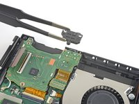
開口ツール、スパッジャー、もしくは爪先を使って、LCDリボンケーブルZIFコネクタ上のヒンジ状のロッキングフラップを持ち上げます。
-
-
この手順で使用する道具:Tweezers$4.99
-
ピンセットを使って、リボンケーブルをマザーボードのコネクタからまっすぐ引き抜きます。
-
-
-
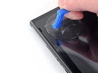
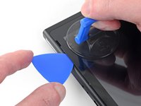
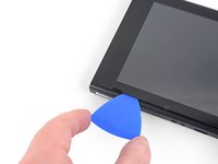
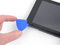
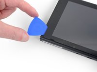
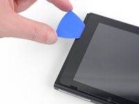
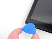
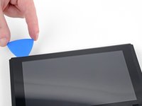
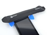
iOpener を温めて、スクリーン下部端に沿って約2分間当てます。留められた接着剤を柔らかくします。
I used a hair dryer because I don’t own a microwave and didn’t like the idea of boiling the iOpener - which apparently doesn’t work that well anyway. For reference, the hair dryer I used was a CONAIR 1875 Styler. I also used an infrared thermometer, which you’ll absolutely need if you’re not going to use the iOpener. You need the infrared thermometer because you must know when to stop heating the digitizer. There are delicate components nestled in the top of the Switch’s faceplate - right where you’ll be putting the heat. To begin:
1. Prepare your work area by clearing the surrounding surfaces of anything plastic, metal, or electronic - surrounding areas are sure to reach temps of up to 110 °F (43 °C).
2. Get something non-conductive like a small cardboard box to rest the disassembled Switch on top of. This will help to target the heat on the specified area, depending on which step you’re on.
3. Grab a piece of cardboard and cut it to the shape of the Switch screen, or around the same size. You will need this cardboard to protect the LCD and delicate internals.
4. Set your infrared thermometer to the side or somewhere close to the spot where you’ll be heating the digitizer.
5. Grab your hairdryer and set that to the side as well.
6. Position the Switch on the cardboard box so that you are ready to begin heating the first side of the digitizer as specified in Step 28. I found that it was easier to have the heated side facing me, so that I can hold the hairdryer more comfortably.
7. Begin heating the bottom of the digitizer, starting on the lowest setting of your hairdryer. You’ll want to hold the hairdryer just close enough that you have about three or so inches between the heat and the Switch itself. Heating the digitizer will take some time, so do not expect the temperature to rise rapidly. A rapid rise in temperature can damage sensitive internal components, even with the cardboard piece in place.
8. After 1 min 30 sec, check the digitizer temperature and make sure that the surface temperature (the opaque black border, not the actual screen) registers at 130 °F (54 °C) or higher. Continue heating on Low until a temperature of 130 °F (54 °C) or higher is reached.
9. When a temperature of 130 °F (54 °C) or higher has been reached, raise the hairdryer another two to three inches from the digitizer. Switch your hairdryer heat setting to High ( or Med, for three-temp hairdryers) and continue heating until a temperature of 161 °F (71 °C) has been reached. Check the temperature every 2 secs to ensure even, consistent heating. Once a temperature of 161 °F (71 °C) has been reached, do not heat the digitizer any further. Doing so could damage the LCD, internal antennas, or faceplate.
10. Repeat steps 6 thru 9 alongside the guide (Steps 28 thru 38) to complete the digitizer adhesive softening process.
Good luck! If this causes anyone any problems, reply here and I’ll try to respond as quickly as possible.
-
-
-
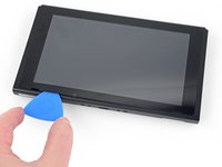
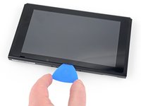
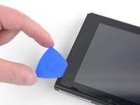
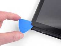
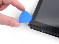
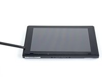
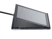
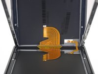
スクリーンの右端をデバイスからまっすぐ持ち上げて、リボンケーブルをフレームに解放します。
What kind of glue is required to re-assembly the screen?
Deedend 77 - 返信
only thing missing. I am scraping the old adhesive off and trying to re-use
UPDATE: So, I was able to peel off the re-apply the old adhesive. It seems pretty secure, but we’ll see. Otherwise, this step needs an additional detail about what type of adhesive would be ideal to finish this.
Hi Jaxon!
Thanks for the suggestion! I added an extra bullet for the adhesive.
How many mm wide Tesa tape should I purchase?
Does anyone know where to find a replacement for the clear adhesive? I successfully completed the repair but the digitizer keeps separating from the screen.
-


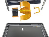
オリジナルのパーツと交換用パーツをよく見比べてください。交換用パーツに付いていない残りのコンポーネントや接着シールなどは、インストールする前に新パーツに移植する必要があります。
このデバイスを再組み立てするには、インストラクションを逆の順番に従って作業を進めてください。
デバイスを起動した後、新しいスクリーンが正しく機能しない場合は、デバイスの電源を切り、バッテリーコネクタを外してから再接続してください。
e-wasteを処理する場合は、認可済みリサイクルセンターR2を通じて廃棄してください。
修理が上手く進みませんか?ベーシックなトラブルシューティングのページを参照するか、このモデルのアンサーコミュニティに尋ねてみましょう。
50 の人々がこのガイドを完成させました。
以下の翻訳者の皆さんにお礼を申し上げます:
100%

これらの翻訳者の方々は世界を修理する私たちのサポートをしてくれています。 あなたも貢献してみませんか?
翻訳を始める ›

4 件のコメント
What size tesa tape best fits the original (not OLED) switch? I have a slightly loose screen and don't want to disassemble to measure without having the right size on hand.
pvantilb05 - 返信
I followed the steps, however the screen only works/lights up if I push on the screen. Any idea what I did wrong?
The Screen and Screen assembly are out of stock...can I buy the LCD, Digitizer etc and assemble them myself?
Kann ich diese Anleitung auch für die OLED anwenden? Habe im INet sonst leider nichts brauchbares gefunden.
Ina Barz - 返信
backup all your sd card data i had to format mine after this tutorial and lost all my game data
JustForThisComment?ComeOn - 返信
do not watch the video! i broke the metal shielding on my switch because they didn't mention a screw!!!
Macro Man - 返信