
MacBook Unibody Model A1278 ヒートシンクの交換

はじめに
手順 1 に進むヒートシンクはプロセッサを冷却して、デバイスをハッピーにしてくれます。
必要な工具と部品
パーツ
ツール


もっと見る
-
-
ケースを閉じたまま、Unibodyを裏返しにして水平に置きます。
-
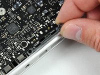
アクセスドアのリリース用ラッチの溝側を押し込んで、出てきた先端をつかみます。 リリース用ラッチが垂直になるまで持ち上げます。
-
-
-
下部ケースをシャーシに固定している次の8本のネジを外します:
-
3mmプラスネジ 1本
-
13.5mmプラスネジ 3本
-
3.5mmプラスネジ 4本
Make sure you have a good quality Phillips screwdriver. Mine had removable tips and had a small play at the connection. As a result I didn't have a good feel and damaged my screws (those securing the fan and the top left in step 23). Game over for me installing new thermal paste...
Be very carefull with your screws! Especially those on the inside.
You can get away with a Phillips #00 for many of the screws involved but the 4 at the bottom case split are likely to strip if you don’t use a JIS #00 or, in a pinch, a Phillips #000.
I used the Phillips #00 tip from my Pro Tech Toolkit, and it worked well enough. But yes, maybe #000 might have been better on the lower row of screws. Note to myself: Always read the comments first.
When replacing these screws, the order to replace them in is as follows:
1, Top left
2. Top right
3. Top center-left
4. Top center-right
5. Bottom center-right
6. Bottom center-left
7. Bottom right
8. Bottom left
I hope this information is helpful.
I followed my usual process of putting in all the screws loosely, then tightening them gradually in distributed pattern, to help ensure that the panel settles in place evenly. But maybe some orders are better.
-
-
-
両手を使って、上部ケースから下部ケースを持ち上げて外します。
Thanks for the guide!
It's implicit in the two photos, but worth mentioning because it blocked my progress in this step for a bit: You have to put the release latch back into its horizontal, closed position before you can lift off the lower-case panel.
-
-
-
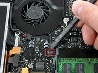
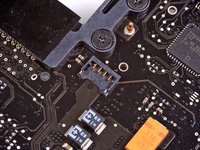
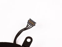
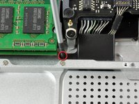
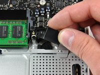
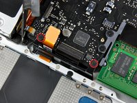
スパッジャーを使って、ロジックボードからまっすぐファンコネクタをこじ開けます。
Solder back to the mother board!
Me too!!! WHAT NOW?
solder back to the mother board
It helped me a lot to look at the closeup pictures of the fan connector socket on the motherboard and the fan connector itself. Then I could figure out where to apply the axial rotating pressure with the plastic "spudger" (a trimmed old credit card). Needed more force to remove the 7-year old connection than I felt comfortable with. The pic's helped with the leverage point to use - just past and under the fan wires BUT not on the board itself.
Excellent guide! Moved fan from MB to MBP and installed new fan in old MB.
-
-
-
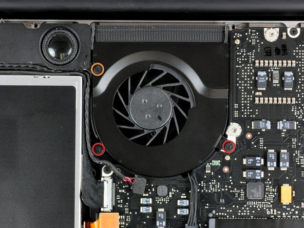
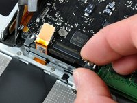
上部ケースにファンを固定している次の3本のネジを外します。
-
5 mm プラスネジー2本
-
7 mm プラスネジー1本
Screws were locktited and I have stripped head of right one while trying to remove it…
same issue as Oleg. have tried multiple screwdrivers and they won’t budge.
-
-
-
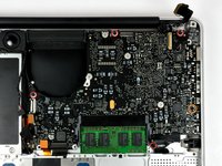
上部ケースからファンを持ち上げます。
One of the screw was messed up. How can I remove it ?
sebmeunier - 返信
I ended up removing the three screws holding down the black gasket that the fan is attached to on the left hand side in the photo. Remove the two screws holding the speaker assembly. then you can remove the 3 screws running vertically down. One is on top of the dvd drive holding it down to the black chassis. dvd drive comes out as well, i followed the specific guide to get that out. Doing this let me flip the mobo out along with the fan, luckily the heatfin is separate from the fan.
Two of my screws did not want to come out when I used Philips #00 and it damaged the screw so now I don't know if I will manage to get it out. What can I do?
Don't know about ruined screw head removal, but for future reference: Place the tool lightly on screw head & rotate axially 'til the tool drops into the screw head for a comfortable, firm fit, before applying pressure & torque for screw removal. If the tool does not drop in the screw head for the comfortable, snug fit, you may have the wrong tool or the wrong size. Try a different size 'til U get the right fit before applying pressure & torque to remove the screw. It can save you grief from a ruined screw head.
-
-
-
-
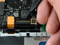
スパッジャーの先端を使って、キーボードリボンケーブルの固定フラップを裏返します。
-
キーボードリボンケーブルをソケットからまっすぐ引き抜きます。
-
キーボードリボンケーブルの右側にある小さなコネクタに別の小さな黒いリボンケーブルが付いている場合は、上記と同じ方法で取り外します。
Trying to get this back in can be really difficult. But it works, just try and try again very patiently. After putting down the retaining flap again, pull a little bit to make sure the ribbon cable is all the way in and fixed.
My late 2008 Macbook 5,1 2.4GHz also had the tiny ribbon plug besides the keyboard ribbon plug polpulated as well (keyboard backlight?) - I missed it blindly following the guide but it made its presence clear when I lifted up the PCB - lucky I was not moving hastily severing the tiny ribbon!
So I added a comment at step 15 as in the guide this tiny plug is clearly not populated in contrast to my Macbook.
Kudos to the author - this guide clearly helped me a lot saving me a lot of time and head scratching.
By the way, minimal thermal paste was found on both CPU and GPU (the original reason I dissasembled my old Macbook) and after I put enough of this thermal transfering stuff on them the Macbook started working much-much cooler after years of hot operation that I thought were due to heavier OSX versions - should have done it 4-5 years ago!
What temp was your Macbook's CPU running at? I have cleaned out exhaust radiator thing, would it be worth redoing my thermal paste as well?
Jake -
@beefmangta With a machine of that age assuming the thermal paste has never been replaced, it is absolutely worth replacing. Certain aftermarket pastes such as Arctic MX-4 (which is available on Amazon) also tend to perform better than stock pastes in many cases.
I accidently cut the tiny cable labeled 21 on the right hand side of the cable highlighted in the photo. It’s for the keyboard backlight. It’s gone obviously but the comp still works without it connected
-
-
-
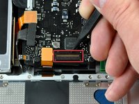
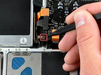
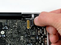
スパッジャーの平面側先端を使って、サブウーファーのケーブルコネクタをロジックボードからまっすぐ持ち上げて外します。
This will easily break, resulting in snapped pins. Will cause right speaker to not function if you don't solder them back on. I don't know how to prevent this from happening, I did just as described in step #21. I even went in from the side as shown in the photo, but probably should have gone in from opposite (RH side in photo) as that's where the pins are.
Broke mine too. With the black foam pad cover and the photo it was impossible to see how this lifted up without ripping out the socket.
-
-
-
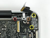
ディスプレイデータケーブルブラケットを上部ケースに固定している次の2本のネジを外します:
-
7mmプラスネジ 1本
-
5mmプラスネジ 1本
-
DC-inボードから7mmプラスネジを2本外します。
-
上部ケースからディスプレイデータケーブルブラケットを持ち上げます。
This step appears to be redundant, but is actually necessary to enable removal of the microphone (later, in step 26).
This step should be clarified, because it otherwise seems un-necessary. Moving step 26 to be after this step would fix the continuity problem.
-
-
-
上部ケースにキーボードフレックスのブラケットを固定している5mmプラスネジを2本外します。
-
キーボードのフレックスブラケットを上部ケースを持ち上げます。
Definitly!! Step 15 is basicially impossible with Step 25 and Step 7 (if you have to reseat the keyboard ribbon cable like I did [Step 15]) in place. Mine presented as dead, thankfully the battery indicator and magsafe worked. But when I reseated the keyboard cable (Step 15) I wasn't convinced so when the power butten did nothing I took a deep breath and went back in. And success was had on the second attempt (psew!).
-
-
-
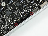
上部ケースにロジックボードを固定している次の5本のネジを外します。
-
3mm プラスネジー4本
-
3.5mm プラスネジー1本
-
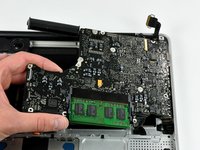
上部ケースからロジックボードの左側端から持ち上げて、取り出します。
On my MacBook, the screw nearest the optical drive is 5mm long.
When replacing the logic board, route the DC-In cable around the front side of the aluminum post.
When re-assembling everything, before performing step 27, it is very useful to perform part of step 23 *first*. Specifically:
- carefully replace the small DC-in boardand secure with the two 7 mm Phillips screws (step 23 yellow)
The small DC-in board is *much* easier to set in place and screw in if you do it before screwing the logic board back in place.
Thanks for the headups! Binya Binya Pollywog! BaBahLouuu BabaLou!!
14vs35 -
Pay particular attention to the routing of the wires from the DC input board to the logic board relative to the wiring for the microphone and the post that supports the right-hand side of the display data cable bracket; route them improperly and you won't be able to get the data cable bracket back into place. Unfortunately the photos don't capture this detail. I also found it easier to position the microphone before fully inserting the logic board, otherwise the leads wanted to torque it about 80 degrees to the plane of the case and no amount of prodding with a spudger could coax it into position.
-
-
-
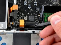
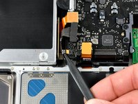
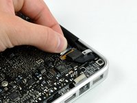
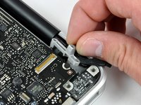
スパッジャーの平面側先端を使って、ロジックボードのサーマルセンサのコネクタをこじ開けます。
Hello!
Like to know what is the use of the second small connection, as the one your deconnecting in this picture, near the heat sink also.
Sorry for my english, I’m french :)
Thank you!
Instead of the connector coming out, both of the wires pulled themselves out of the connector, breaking it. I will just put them back in and hope it works out. Be careful!
-


デバイスを再組立する際は、これらのインストラクションを逆の順番に従って作業を進めてください。
デバイスを再組立する際は、これらのインストラクションを逆の順番に従って作業を進めてください。
48 の人々がこのガイドを完成させました。
以下の翻訳者の皆さんにお礼を申し上げます:
100%

Midori Doiさんは世界中で修理する私たちを助けてくれています! あなたも貢献してみませんか?
翻訳を始める ›

6 件のコメント
Great guide! Helped me deep-clean the MacBook and reapply thermal paste to the CPU/GPU. I found it better to do step 15, the keyboard ribbon cable before screwing the keyboard flex bracket back on. The cable is fragile, and it's hard to get back in, so I recommend a fair amount of caution. The same goes for the IR sensor ribbon cable - put it on before you place the logic board down, by turning the logic board to best insert the cable. Also, remember to use the exact correct screwdrivers! If not, you risk stripping the screw heads, which will cause you an extreme amount of frustration later down the line. I completely stripped one of the screws holding down the fan previously, and it took me an hour just to get it off. Other than this, the guide is perfect for all your needs.
Great guide. Laptop was struggling encoding a movie for my iPad. Temps sitting close to 100°c and fan maxed out. After replacing thermal compound and giving the insides a good dust it’s now encoding again but 20-30°c lower and fan isn’t going crazy yet.
Watch out when doing this I did this last night and my mac book stopped charging. When I get home later I will diagnose the issue but if I am correct I just need to re seat the cable.
The guide is missing a vital step: before lifting the logic board, you need to disconnect the cable on the top right underneath.
you mean step 26?
Excellent guide. Thanks OP!
This is not a a1278 unibody MacBook Pro. A1278 MacBooks backs are one solid metal piece not two separate pieces. This guide is for a different MacBook Pro.
Brad Burgeson - 返信
This guide isn’t for a pro; it’s a MacBook unibody.
Nicholas -
So, it turns out that Apple used the model code A1278 for quite a few different Mac models, including both Pro and non-Pro versions! This guide is for the non-Pro Macbooks. There’s also one for the Pro models with the same A1278 identifier.
tempelmann - 返信