はじめに
このガイドを参照して、MacBook Air 13インチ Early 2017 上部ケースを交換します。
必要な工具と部品
-
この手順で使用する道具:P5 Pentalobe Screwdriver Retina MacBook Pro and Air$5.99
-
P5ペンタローブドライバーを使って、下部ケースをはずしてください。ネジは次の長さに分かれます。
-
9mm ネジー 2本
-
2.6mm ネジー 8本
-
-
-
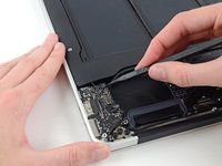
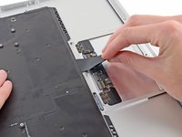
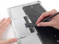
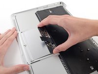
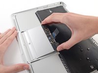
ディスプレイと下部ケースの間に指を入れ、上に引っ張って下部ケースを本体から外します。
-
下部ケースを取り外して脇に置きます。
There is a nub on the inside of the case which is attached to the battery. When you try to pull it open, it appears to be attached to the plastic casing of the battery, which sometimes splits. I gently unhooked the nub from the battery before removing the case fully. This seems to happen if the battery has suffered some drop damage (plastic parts broken around screws and parts of plastic frame split). Just an FYI in case your lower case doesn't pull away easily.
To add - the slim 1cm tab “nub” is on the centre of the back cover & fits into a hole in the battery frame. I ran my fingers around the whole of the cover to eventually here it click out.
nijafe -
So this is a legit back cover for MacBook Air?
I bought the part and tools from iFixit and followed the directions. The mechanical part went smoothly - maybe 10 minutes to disassemble/replace/reassemble.
Getting Catalina (the current MacOS) to install was not working until I used Cmd-Opt-R (as noted in the OWC paper sheet that came in the box) which brought up the proper installer - I believe from a pre-prepared bootable SD card but it’s hard to say. From there the install succeeded taking ~1.5 hours.
Beware that (a) the install requires a working internet connection for verification and updates, and (b) the system must have been running at least macOs 10.13 (High Sierra) before the install in order to have an EFI BIOS that recognizes the SSD.
Lance Berc - 返信
Thanks for the detailed photos. When repairing equipment, I don’t really like to disassemble plastic parts, they can be damaged, but your screenshots help a lot. For my studies, I am writing an essay comparing the reliability of laptops from various manufacturers and the complexity of their repair, maybe it will be useful for someone to check the essay for plagiarism here essay checker, when comparing different manufacturers, I understood why people love Apple so much. The minimum number of failures. Of course, repairing it in an official service is not cheap, but with the help of such detailed instructions, you can do it yourself and save a lot.
The screwdriver bit to use on these case screws is not named, but I found that my "CR-V 1.2" did the job nicely.
The driver for the screws inside the case are named, as "T5".
-
-
-
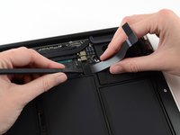
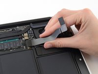
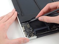
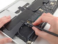
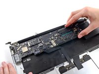
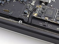
バッテリーコネクターに取り付けられた透明なプラスチック製のプルタブを掴み、Airの前端に向かって引っ張り、バッテリーをロジックボードから外します。
how does a person put the battery connector back in?- that is the only thing i’m afraid of touching after putting new fan in.
I found it was possible to put the battery connector back in as the last step, however having gone through that and found it to be a little challenging, I would actually recommend attaching the battery connector before screwing back in the bracket. That way you’ll put a lot less stress on the connector cable.
When you are plugging the connector back in, make sure to give it some extra pressure to make sure it is all the way in. It may look like it’s in but needs to be pushed harder!
After disconnecting the power, you may skip directly to step 18. I don’t know why someone would think it necessary to disconnect all the other stuff. There is no need whatsoever to do so. The more things you disconnect, the more things you risk damaging. Many of the parts in steps 4 through 17 are quite delicate, and easy damaged.
The screw in step 18 is easily accessed without removing even the rubber gasket. Regarding step 18, only remove the screw. (This screw is rather long, with long threads.)
It’s helpful to take photographs of this area before removing the screw, so you’ll know what it’s supposed to look like when you put it back together.
There are only 16 steps in this repair process. I wonder whether you are commenting on a different repair.
Gyandev -
What if your battery doesn’t have that clear tab?
Yep, exactly the issue that I have
Unscrew the battery first, then let the cable flex out a little. Use a spudger or small pick to push the connector out from the board.
Nathan -
Where can i buy the battery connector?
Macbook air 2015 battery connector where can I purchase?
-
-
-
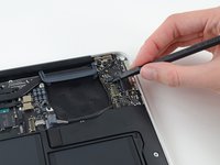
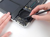
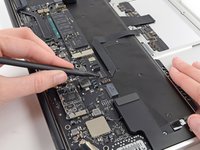
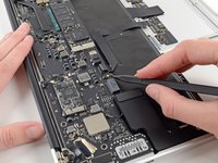
スパッジャーの平面側先端を使って、I/O ボード上のソケットからI/O ボードケーブルのコネクタを跳ね上げます。
When putting this back together, be careful you don’t flip I/O board cable. It will fit, but the computer will not work. You’ll know it’s wrong if it covers the fan.
-
-
-
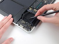
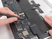
ファン上部に固定された接着剤からゆっくりと丁寧にI/O ボードケーブルを解放します。
the instructions should really indicate you’re only disconnecting one end of the cable. you disconnect the other end in step 6.
Bonjour,quand je retire la nappe de la carte E/S , l’éclairage de l’écran s’affiche mais quand je remets la nappe de la carte E/S ,j’ai un écran noir.J’attends votre réponse.Cordialement.
I literally did this wrong just like you warned not to! Very easy to do…
I watched the video twice and went really slowly through steps and it works!!! It was a little scary but we got through it! Thanks so much!!
20.00000.000$
Dewi Oasis - 返信
-
-
-
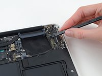
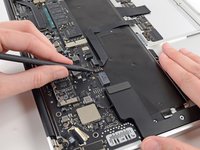
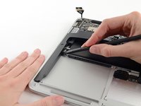
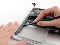
スパッジャーの平面側先端を使って、I / Oボードのケーブルをロジックボードの接続部付近に向けてゆっくりと跳ね上げます。コネクタの両側から上向きに押し上げて、ソケットから外します。
-
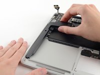
I/O ボードケーブルを取り出します。
pour le remontage
de mon coté tout c’est bien passé, il faut juste bien vérifier la nappe de la carte E/S soit à l’endroit, car sinon l’ordinateur refuse de démarrer ( se référer à la photo du coup )
-
-
-
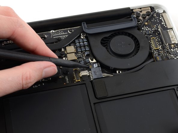
スパッジャーの先端を使って、ファンケーブルのZIFソケット上の固定フラップを注意深く跳ね上げます。
The end of that cord slips into the channel whose lid you just flipped up. Don’t forget to re-insert that when reseating the fan and before flipping that retaining flap closed, it’s easy to miss and should have been part of these instructions, ifixit!
Thank you so much! Without your comment, I wouldn’t of realized that the ribbon cable is supposed to go into the socket (I know, dumb mistake now that I think about it). You also made me go back and correctly insert the microphone cable. Cheers!
After my repair, my fan is super loud now! Any tips?
I didn’t find any need to unplug the fan. All I did was remove the three screws which hold the fan to the case and gently fold the fan out of the way. All you are trying to do is gain enough room to route the camera cable into the little cut-out in the I/O board so it can go below the board along the edge of the fan.
I agree, BobY. I too didn't disconnect the fan cable. Those retaining flaps are so tiny it's hard even to see whether or not they are flipped up, so I was happy not to have to deal with it. That meant, however, that I had to be extra careful not to stress the fan cable when removing the fan (or more precisely, just lifting it out of the way rather than removing it completely), but I seem to have succeeded.
Gyandev -
I wish I'd read these comments before unplugging that cable. I can't figure out how to reseat the cable so I can close the retaining flap. It would help if I could see it better, or had a better idea of how it was connected before I unplugged it.
-
-
-
ファン上部についているゴム製ガスケットの接着剤を剥がします。
When putting the computer together, pay attention to the placement of the gasket. It has a pin on the left side the enters the main board from the bottom. The right side straddles the tip of the heat pipe and there is a photo later on with close-up.
-
-
-
上部ケースにファンを固定している次のネジを外します。
-
5.2 mm T5トルクスネジー1本
-
3.3 mm T5トルクスネジー1本
-
4.4 mm T5トルクスネジ(ショートヘッド)ー1本
I was unable to remove the 4.4 mm screw with the T5. I needed to use the T4 to get a grip so I didn’t strip the head.
The 3.3mm Torx is actually a 4.4mm
-
-
-
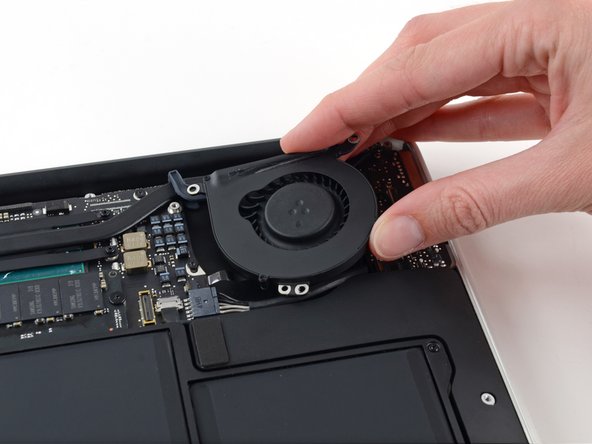
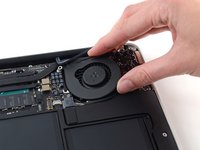
I/O ボードの側面からファンを持ち上げて、上部ケースからファン全体を取り出します。
-
ファンを取り出すには、ファン用リボンケーブルの接続を外さなければなりません。ケーブルを他のケーブルに引っかけないようにご注意ください。
I didn’t find any need to remove the fan. I had no trouble routing the camera cable between the fan and the I/O board by just tilting the edge of the fan nearest the I/O board up and out of the way (pretty much what is being shown in the picture above).
I agree. I had to put something under the tilted (not removed) fan in order to have room to work, but it went okay.
Gyandev -
I removed it but it was a little tricky getting the ribbon cable back in. I was afraid it would break but it finally seated after a little wiggling.
-
-
-
I/Oボードのパワーケーブルをロジックボード上のソケットから引き抜いて、接続を外します。
The connector has a latch (at least mine does) that prevents it from simply sliding out. To release it, I inserted a 5/64 flathead screwdriver to lift the edge of the socket. Then the jack and cable easily slides out.
-
-
-
スパッジャーの平面側先端を使って、I/Oボード上のソケットから左側スピーカーケーブルコネクタを持ち上げます。
when i did this the whole socket came off the board and i had to get a replacement i/o board. Be warned, do this very carefully and avoid my mistake
If you are here to replace the logic board, you can skip steps 12-16, they’re unnecessary to replace the logic board.
maccentric - 返信
How do you put this back?? I’m struggling to figure out how to get the connector back into the socket of the new I/O board
You just line it up and push it down into the socket. Straight down, not sideways.
For Display disassembly you can skip this step.
I replaced a broken display of a MB Air with the functional of another MB Air. I removed the I/O board while disassembling the first Display, then I saw the comments so I tried it out while disassembling the second display. Worked out totally fine and saved me some time.
-
-
-
スパッジャーの先端を使って、マイクリボンケーブルのZIFソケット上の固定フラップを注意深く跳ね上げます。
There was black tape covering this socket. It was attached to the ribbon tape. I needed to pull up the tape covering the socket to expose the retaining clip.
Thanks Brant!
The note about the black tape should be in RED in the main text above. I broke off the connector thinking the tape was part of the cable assembly. Always read the comments. Always. : )
Ripped the connector off the picture was too small and I couldn’t see what part to lift.
If you click on the picture, you'll get a nice detailed blown-up view.
Steps 13 and 14 are unnecessary
-
-
-
I/Oボードを上部ケースに固定している4.1mm T5トルクスネジを1本外します。
Steps 14-15 & 28-29 seem unnecessary. I managed to replace the logic board without removing the I/O board or right speaker, although that means the logic board cannot be removed easily - the right rear corner is hindered by part of the chassis so that the edge of the logic board facing the battery should be lifted gently first and then the board be slid away from that obstructing part.
Exact, the step 14 is unnecessary
-
-
-
-
I/Oボード上の凹みからカメラケーブルを慎重に引き戻して、スパッジャーの先端でケーブルを邪魔にならない位置に押さえます。
This is really tricky. I couldn't de-route the cable as long as the I/O board was still in place. Had to lift the board mostly out of place in order to get enough slack in the cable to de-route it. Otherwise, I was going to have to force the de-routing, which seemed like a really bad idea.
-
-
-
I/Oボードをロジックボードから持ち上げて、上部ケースから引き抜いて取り出します。
-
I/Oボードを取り出すと、マイク用リボンケーブルの接続を外さなければなりません。ケーブルを引っ掛けないようご注意ください。
Nor for the logic board removal
maccentric - 返信
The back end of the microphone riibbon cable may be stuck down with a bit of glue under the flap. You can gently loosen it with a flat spudger.
how do I reattach the riibbon cable now that the adhesive has been removed?
I wonder if you weren't replacing the I/O board, BobY, but rather were doing some other repair. I say this because the microphone ribbon cable has to be disconnected from the I/O board in order to replace the I/O board, which is the repair that I was working on. And that disconnect/reconnect was definitely the fussiest part of this entire repair. Such tiny components to handle! In the end, I had to resort to using a tweezers, and even then I wasn't sure that everything was fully seated and secure.
Gyandev -
I wasn't replacing the I/O Board, I was replacing the entire Display Assembly--I got to this step within the instructions for replacing the Display Assembly. Maybe iFixit uses the same comments if they link to this same step from a different set of repair instructions? My comment was meant to convey you definitely don't need to remove the I/O Board to replace the Display Assembly.
BobY -
I got to this point (Step 16) within the instructions for replacing the Display Assembly, which is where I'm entering this comment. My comment was meant to convey it isn't necessary to remove the I/O Board to replace the Display Assembly, but you certainly would need to remove the I/O Board to replace the I/O Board.
-
-
-
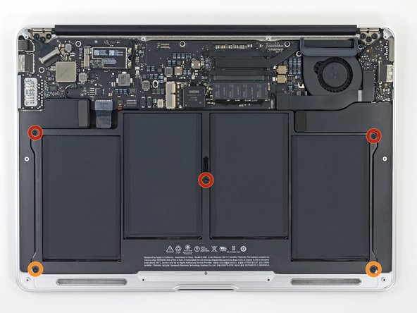
バッテリーを上部ケースに固定している次の5本のネジを外します:
-
6.9mm T5トルクスネジ 3本
-
3.0mm T5トルクスネジ 2本
what is that little hole or clip in the middle o battery?
Edy Surpat - 返信
There’s both a hole for a screw and a clip to hold the bottom case
Hello,
the battery is now delivered with a transparent plastic taped allover the new battery.
is it needed or shall it be removed
kind regards
Hello,
If the plastic is easily removable from the battery, it should be removed. However, if the plastic is glued onto the battery, do not remove the plastic.
The centre screw (of the three 6.9mm T5 described above) seems to be a bit thicker diameter than the other two corner (6.9mm screws - although I don't have a tool to make precise measurement). Replace this thicker screw to its centre position on the battery.
Not having a T5 bit, and somewhat dismayed at needing such an odd size of a familiar driver, I found aT6 bit worked fine for me...
I accidently broke off a 6.9 mm T5 Torx screw the one that goes in the center of the battery. Is it a big deal if all the other screws are in place holding the battery as well at the back end case? It seems secure but a piece of the screw that broke off is stuck in the center, and I can’t take it out to replace it with a new one. Is it a big deal? I powered on the computer and the battery is working at 39% to start
-
-
-
ロジックボード側の端からバッテリーを持ち上げて、上部ケースから取り出します。
-
100%になるまで充電します。充電後も最低2時間はプラグを繋げたままにします。それからプラグを外して、通常通り使用しながら、自然に放電させます。バッテリー残量小のサインが表示されたら、これまでの作業を保存して、スリープ状態になるまで放置してください。スリープ状態に入ったら、少なくとも5時間置きます。それから一気に100%まで充電します。
-
新しいバッテリーを装着後、通常通り作動しない場合は、MacBook ProのSMCをリセットしなければならない可能性があります。
Personally I would like a short description on why we have to calibrate a brand new battery for what reason?
@albertnumber1 You can find a detailed explanation of calibration here. The short(ish) answer is that the battery charge % reading on your device is really just a guess, one that is generated by a mathematical model of what’s going on inside the chemical battery. That model needs data points (like full charge and discharge flags) in order to work correctly. Without calibration, nothing bad will happen, but you may get some unreliable battery % readings.
1. Glad someone was able to clear up the reason we need to calibrate
2. During the process, if for some reason, say my cat waltzing all over my desk, disconnects the magsafe for a moment while in the final full charge cycle, what impact would this have?
The replacement battery’s connector didn’t align with the port as easily as the original’s. Instead of pointing straight back from the battery, the cable pointed at a significant angle. In order to connect the new battery, I had to hold it a slight diagonal angle while connecting it, before placing the new battery into the chassis and securing it.
After replacing the battery, the laptop (MBA early 2015) shut off immediately whenever it was unplugged from the MagSafe connector, despite reporting a full charge. To resolve this, I performed an SMC reset: I re-opened the case, unplugged the battery, held down the power button for 5 seconds with the battery unplugged, then re-connected the battery, re-attached the lid, and pressed the power button again. It immediately booted up as expected on battery power.
I found these two little broken tabs under the battery. Not sure where they came from, but Ididn’t put them back in anywhere.
These are from the old battery. Not totally necessary.
Good opportunity to blow or brush away some accumulated dust from a unit like mine (5 -6 years service) when the battery is out. Also at this time, used the thin probe tool to ream out some debris from the rim of the base.
The replacement battery cable seemed too long to fit well but when I examined the original, I noted a distinct v kink downwards in that one. A gentle push down in the middle formed a V and permitted the new cable to fit Presumably without harm..
howardmat3 - 返信
The instructions on this step say to remove the plastic film on the replacement battery, but the introduction says to leave it on. Which step is correct?
Hi William!
Good question! If the film is lightly adhered, you can peel and remove the film.
Hi how can I discharge the battery (MacBook air 2017) quickly as the battery has swollen and I need to get it out, at the moment I am running lots of apps but it still shows 6%?
max screen brightness and run some cpu benchmark
Shorting the battery is very dangerous. Leave the computer on until it shuts down on its own.
Good morning, I just replaced my first battery. The light on the magnet is red now. Will that color change to green to inform me that it is fully charged? Thanks, Julie
Re: leaving it unplugged for 5 hours after the battery goes flat - isn't that a bad thing? I thought Li-ion batteries get damaged by letting them go completely flat?
I have the same question, but from what i read the battery is still on 10% when the mac shuts down (to keep the battery healthy, so the 0% on the mac display is actually not the real battery charge)
Does anyone know what the four white (or red) dots on the underside of the battery mean?
Those are the liquid damage detectors. If they are red it means liquid has gotten into them. Always a bad sign
I've got a problem with the second MBA 2017 I did a battery replacement on. Replaced the battery, charged to 100%. Drained the battery and waited 5+ hours. Now it's stuck on 1% and won't charge. I've tried SMC reset by opening it up again, disconnect the new battery, hold the power button for 5 sec, connect the battery again but without any luck. Any suggestions?
Seems like a power cycle fixed the issue (turning the computer off, unplugging the MagSafe, holding the power button for 10 sec, plugging MagSafe back in).
Installing and conditioning the new battery was a breeze with your instructions and tool. But I get a message saying the date/time was set incorrectly. I could not reset it using the date/time in system preferences and the laptop was running hot with the fan running at full blast. Instead I had to shut it down and restart it in safe mode by pushing the shift button when I heard the start up chime and releasing it when the Apple logo appeared. Once in safe mode the date/time was correct and I restarted in normal mode. It's all good now. iFixit's comments allude to chip dependent issues and your should look at their detailed comments if you are having issues on restart after install. Thanks for a great product!
-
-
-
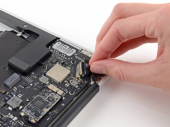
スパッジャーの平面側先端を使って、 AirPort/Bluetoothカード上のソケットから両方のアンテナケーブルコネクタを持ち上げます。
One of my terminals is broken. What solutions do you recommend me
Omar Lopez - 返信
You’re actually pushing the connector from side to side toward the front of the case (or towards the track pad). It’s not a vertical motion at all.
Jay Quilty - 返信
I’d also mention to be careful taking these off and putting them back on. I also accidentally pulled a terminal off it’a cable.
If the process is taken to replace the top case, you can leave the AirPort card hanging from the antenna wires. Only remove the card’s retaining screw and slide the card to the right (direction of the antenna connectors) to separate it from the main board.
-
-
-
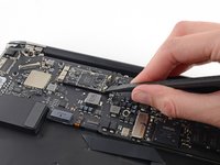
スパッジャーの先端を使って、カメラケーブルコネクタの接続を外します。
-
カメラケーブルをI/Oボードの表面と並行に、本体の前面端に向けて引っ張り、接続を外します。
You’ve missed a whole section here on removing the fan. It’s still present in Step 19 pics, but gone by Step 23. It’s not that it’s difficult to work out how to do it. But, when reassembling and following the steps in reverse, it’s handy to know when to use which screws!
Ah! –my bad. The steps for removing Fan etc. are there –up round Step 13. It’s just your photos that are slightly out of sync, as it’s back in place again by Step 19. So, while working in reverse, it looks like it’s not been covered.
On getting it on — i feel it's implied by the word "push” you can walk it out with the spudger. I couldn't wanage that, and instead walked it out by taking the cord between my index and thumb and walking it out by pulling it to the right and then the left repeatedly in a
-
-
-
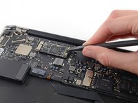
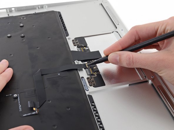
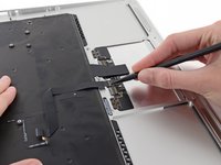
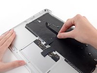
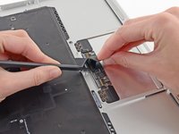
スパッジャーの先端を使って、キーボードバックライトのリボンケーブルのZIFソケット上の固定フラップを持ち上げます。
-
スパッジャーを使って、キーボードのバックライトリボンケーブルをソケットから引き抜きます。
Do you know where i can buy the retaining clip ?
Not sure you can. I’d just use some kapton tape to hold it in place and call it good.
-
-
-
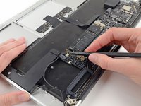
スパッジャーの平面側先端を使って、ロジックボードのソケットから右側スピーカーのケーブルコネクタを持ち上げて、接続を外します。
What is this cables for?
It’s a speaker cable
This is the one that gave me the hardest time!!! It does pop up and out tho.
-
-
-
上部ケースにロジックボードを固定している、6.3mmT5トルクスネジを6本外します。
When re-assembling the motherboard, attach all 6 screws but do not completely tighten yet.
First make sure the rubber gasket is sitting properly, that the 7th screw hole (from Step 18) is properly aligned, and the Airport wire is sitting properly and also not caught under the heat sink.
Once everything is well aligned, start tightening the screws while watching out for the alignment. I found it useful to keep an eye on screw-hole from Step 18 as a reference.
Going in this order, there is a 7th screw securing the logic board to the frame; the heatsink is secured to the logic board with 4 screws, and secured to the frame with 1 more screw. Either take the heatsink off first, or remove that last screw underneath two small black wires, next to the left (as viewed when using the computer; if the computer is flipped over with the cover off and the monitor hinge end of the computer farthest from you, it is in the far right corner) set of three big torx screws that hold the hinge in place. The exact location of this screw is pictured in step 35's second picture; the screw goes through the loop visible below the rubber fan insulator. Scoot those 2 li'l wires out of the way and remove that screw, then the logic board comes right out. If this isn't clear, please let me know and I'll try to describe it better, or add a photo. If I'm posting this to the wrong instruction page, let me know; I was pretty sure I correctly identified my rig, but if not, sorry for the N00bage.
I got an extra screw hiding under the rubber gasket holding the end of the heatsink to the chassis. Ended up bending the heatsink a little cause I wasn't looking for it.
“Samsung RAM module”… do you mean the SSD? That stick of NVRAM is totally your hard drive.
Exactly, he means SSD (storage) the RAM (memory) is soldered to this 820-00165 logic board. Also on this model the 2015 MBA there is no logic board retaining screw under the SSD
-
-
-
アンテナケーブルリテイナーと左側のクラッチヒンジを上部ケースに固定している、内側の4.9mm T8トルクスネジを2本外します。
This is the same screws as step 17.
Joseph Lee - 返信
Good catch! We did some sleuthing and it looks like a couple guides did indeed have an extra section of steps! All better now =)
In my computer these screws were the same size as the other side’s hinge screws. All 6 are the same size.
-
-
-
アンテナケーブルのリテイナーをわずかに押し出して、上部ケースとヒートシンクの先端を固定している3mm T5トルクスネジを外します。
It’s not clear what you mean by “This step is not needed.” If you want to remove the logic board from the upper case in order to put it onto your replacement upper case, you will have to remove this screw.
This step is only needed if you’re replacing the ENTIRE top case. Simply swapping out the trackpad unit does not make this step necessary. This entire tutorial assumes you’re replacing the entire top case which is an expensive mistake if you’re simply replacing the trackpad and/or keyboard. The keyboard is removable as well despite those many tiny rivets. Save money and time by not replacing the entire top case for a bad trackpad and/or keyboard. I needed to accomplish this step because I also removed and replaced the keyboard.
NOTE: There is a sort of clamp/washer attached to this screw that I didn’t know about until I flipped the laptop up on its side and it fell onto the desk. Also: you need to reset it *before* the motherboard
In my computer this screw was not there, nor was a related washer. I got it used so perhaps someone has already been there and did not replace the screw.
Also, the photo here shows how this end of the fan gasket is placed
.
-
-
-
スパッジャーの平面側先端を右側スピーカーの下にスライドして差し込み、接着剤を緩めます。
-
右側スピーカーを、上部ケースから取り出します。
You don’t really *have* to remove the speaker, especially if your replacement upper case assembly already includes the speakers.
I found the same. If you already have speakers in your new upper case, you can leave them. When you put the logic board back in, it will be a tight fit. I had to start with the corner near the right hinge (the Thunderbolt port corner) and work it in to place.
If it is difficult to remove the speakers you can use Isopropyl Alcohol to loosen the adhesive holding the speakers in place. Make sure to keep the Isopropyl Alcohol away from the speaker itself.
BluRepairs - 返信
-
-
-
慎重にロジックボードアセンブリを上部ケースから取り出します。ケーブルが絡んでいないかご注意ください。
-
ボードから緩いケーブルを離して、ボードの下に挟まらないようにします。
-
2番目の画像でハイライトされているように、アンテナケーブルがそれぞれの切り欠きに挿入されているか確認します。
It’s probably worth mentioning here that during reassembly you want to tuck the rubber gasket under the extension of the heat sink that the fan slots into.
-
-
-
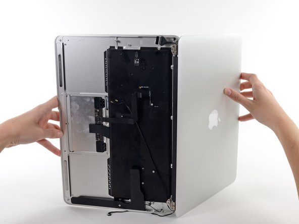
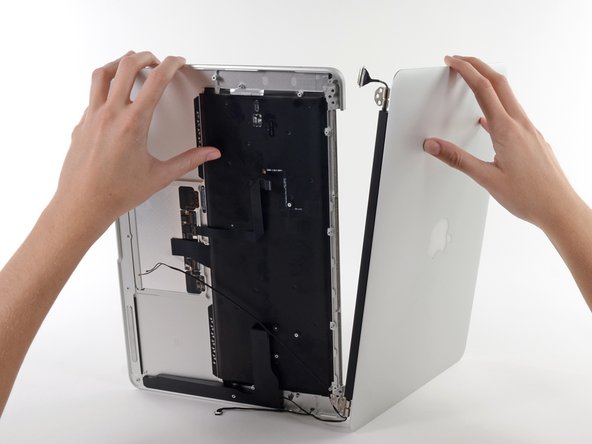
Airのヒンジが、凹みからスライドして外れるまで、ゆっくりと開きます。
-
2つのディスプレイヒンジが上部ケースから外れたら、ディスプレイを外して脇に保管してください。
MBA 2017: At this point I had to deroute the antenna cable from a channel along the back edge of the the upper case. Good to make note of this routing.
-
-
-
スパッジャーの平面側先端を使って、左側スピーカーを上部ケースに留めている接着剤から持ち上げます。
-
上部ケースから左側スピーカーを取り外します。
Not necessary to remove this. I was replacing a top case that included the speakers.
Same as the speaker in Step 29, which seems like it can also be left in place.
Replacing the entire top case is not necessary with the common spilled beverage situations. You can purchase a trackpad as well as keyboard for much less than the cost of an entirely new top case. Why replace the expensive aluminum top case unless it is itself broken which is unlikely.
If it is difficult to remove the speakers you can use Isopropyl Alcohol to loosen the adhesive holding the speakers in place. Make sure to keep the Isopropyl Alcohol away from the speaker itself.
BluRepairs - 返信
-
-
-
スパッジャーの平面側先端を使って、上部ケースの左側にマイクロフォンを固定している接着剤を剥がします。
-
必要に応じて、iOpenerもしくはヘアドライヤーを使って、接着剤を若干温めると作業がしやすくなります。
-
上部ケースからマイクロフォンを取り出します。
If you’re replacing a top case with one provided by Apple, you won’t need to transfer the microphone to the new top case.
Hot air really helps here.
I really sweated over removing the microphone, but as Carroll mentioned, it’s not necessary since it was supplied with the iFixit upper case. Thanks, because it was a b*tch to remove and I probably damaged it in the process. Even with heat.
I did not have a mic in my Ifixit. Am I assuming I need to put it back? with adhesive
-
-
-
スパッジャーもしくは指先を使って、トラックパッドのリボンケーブルのZIFソケット上の固定フラップを持ち上げます。
-
トラックパッドのリボンケーブルを、Airの前面端に向けて、ソケットからまっすぐ引き抜きます。
Please note that if you are replacing the keyboard you must save this cable for the new one!
In keyboard replacement, don’t need to take the cable off at all.
-
-
-
スパッジャーの先端もしくは指先を使って、キーボードのリボンケーブルを片手で慎重に持ち上げながら、キーボードリボンケーブルのZIFソケットから固定フラップを持ち上げます。
-
キーボードのリボンケーブルを、Airの前面端に向けてソケットから引き抜きます。
I could not figure this out from the description. I was concerned about pulling too hard, so I elected to leave the ribbon cable in place until I removed the trackpad. It became obvious what to do at the point. The fact that the retaining flap is entirely hidden under the ribbon cable, and is on the keyboard side of the connector, was lost on me.
-
-
-
次の7本のネジを外します。
-
上部ケースにトラックパッドを固定している1.6mm プラスネジを6本外します。
-
上部ケースの前面端付近のホールから1.4mm T5トルクス止めネジを1本外します。
On The MacBook I worked on. It was not necessary to remove the 1.4mm T5 torx set screw. Which I found out after I broke a T5 bit in it.
BROKE my T5 bit on this “set screw” too. Correct, it isn’t necessary to remove, I recommend removing it from the steps.
Broken bit is perhaps a novice move by me, perhaps a cheap Torx screwdriver. Certainly made the rest of the repair dicey.
Yep the replacement case I got had one already installed; you can remove the trackpad with this screw in place, so you may not need to remove it.
John Noble - 返信
I had trouble removing the 6 Phillips screws. Even though I have a Phillips size 00 screwdriver it is not engaging the screws properly — I cannot get them to turn without stripping. I ordered the philips 00 screwdriver from iFixit and am HOPING that solves it.
Yes, make sure you have a good quality screwdriver that gets excellent purchase on these screws, and bear down to make sure you don’t strip them. I stripped one and had to drill it out with a 1/16” carbide drill bit. I’ll end up with only two screws on one side but I imagine it should be OK.
I was able to cheaply replace the keyboard as well as the trackpad, both without replacing the expensive aluminum frame. I followed these steps and then added a few to the end. I was able to easily remove the keyboard black cover/film by lifting the adhesive edges from the case. Then I removed the white backlight layer. Unlike earlier Macbook Pros, this Air model has the keyboard both screwed AND riveted to the aluminum frame. No biggie! I removed the tiny black screws from the keyboard edges then used pliers to pull the keyboard away from the aluminum frame. With this method I removed about 80% of the rivets which left perfect holes for the screws that came with the keyboard. After seating the new keyboard unit I was able to fasten it to the aluminum frame with screws on the keyboard edges as well as in the popped rivet holes. This tutorial can be modified near the end to create a keyboard replacement tutorial. See Rivet-pop method on YouTube, 20min into this video:
All the steps went swimmingly, until I got to this step. As soon as I put in the Phillips 00 screw driver, I immediately knew that one of the Phillips screws was already partly stripped - probably during original assembly. Sure enough, no engagement. Does anyone know how to remove such a tiny stripped screw?
The Phillips #00 recommended in the “Tools” section did not work for me and almost stripped the screws. I tried a Phillips #000 and it worked perfectly.
-
-
-
キーボードに最も近いトラックパッドの端を上部ケースの奥から持ち上げて、上部ケースに装着したブラケットから外します。
-
上部ケースからトラックパッドを取り出します。
-
上部ケースが残ります。
I’m disappointed that you didn’t touch on the keyboard removal process, even if it was touching on it without images.
-


デバイスを再組み立てする際は、これらの手順を逆の順番に従って作業を進めてください。
e-wasteを処理する場合は、認可済みリサイクルセンターR2を通じて廃棄してください。
修理が上手く進みませんか?まずはベーシックなトラブルシューティングを試してみるか、このモデルのアンサーコミュニティに尋ねてみましょう。
デバイスを再組み立てする際は、これらの手順を逆の順番に従って作業を進めてください。
e-wasteを処理する場合は、認可済みリサイクルセンターR2を通じて廃棄してください。
修理が上手く進みませんか?まずはベーシックなトラブルシューティングを試してみるか、このモデルのアンサーコミュニティに尋ねてみましょう。
14 の人々がこのガイドを完成させました。
以下の翻訳者の皆さんにお礼を申し上げます:
100%

Midori Doiさんは世界中で修理する私たちを助けてくれています! あなたも貢献してみませんか?
翻訳を始める ›

4 件のコメント
Excellent guide. As there was no guide for mainboard replacement I used this one up to step 30, perhaps there should be a guide? The most difficult part for me was getting the rubber fan gasket to sit where it needed to during reassembly, perhaps a detail photo of this when the PCB is floating would be a benefit. I also had another small rubber piece come loose from somewhere and was unable to determine where it was supposed to live. It was about 1.5 cm long, and had an extruded channel in it, like perhaps it was supposed to protect and edge or a cable… seemed to fall off from somewhere on the LCD connector side of the board, but I don’t see it in any of the photos included and nothing was obvious.
I used this as a teardown and then in reverse a rebuild guide. My mac was water damaged and I replaced the logic board using this guide. And it worked! Thanks so much to the author
Pulling the fan cable out was terrifying but you actually just pull on the cable itself. No way to get any leverage at the connector to dislodge it. Did come out easily but like I said, scared me!
allison - 返信
Draai de schroefjes voorzichtig los en leg ze op een stabiele plek neer en let erop dat de schroefje een verschillende lengte hebben.
bwgvanderveer - 返信
I thought I could replace my 256 Gb SSD with 512? regards
ola m - 返信
Do you have good Test Point Voltages? It appears there are silver colored Test points on the I/O Board. I am working on a water spill and trying to troubleshoot if both the I/O board and the Logic need replaced.
andrew - 返信
It's probably not necessary but may be a little safer to completely discharge the old battery before replacing it.
Larry Smith - 返信
tell a model that was not inferior to the speed of the one in the laptop.
Thank you
ilyabuhov - 返信
Do i need to order tools separately to replace the battery i just ordered?
anne uhlir - 返信
im looking for a Logic Board for a
Apple - MacBook Air® - 13.3" Display - Intel Core i5 - 8GB Memory - 128GB Flash Storage (Latest Model) - Silver Model: MQD32LL/A
Any help is appreciated.
Jamie Comstock - 返信
P5 pentalobe screwdrivers are too big! The correct size for these screws are p4 pentalobe. P5 pentalobe was just able, with difficulty, to turn some of the screws. If the screws were at all tight, my p5 was unable to get them out, and started to strip the screws. A p4 screwdriver fit better and removed the screws with ease. (I was using high quality Wiha brand screwdrivers.)
William Skinner - 返信
I had same experience (with MacBook Air 13-inch Mid-2012) … had to get P4, which worked swimmingly
eric -
Very simple installation. The screwdriver heads were exactly what we’re needed, one head for the outside case screws, the other for the screws holding the battery in place. The computer started right up. Now to see how the battery holds up, but I have a good feeling about this!
Dennis Eaton - 返信
My P5 and the T5 worked perfectly with my early 2015 Air 13”! And it is super fast! Thank you iFixit!
Pennny Beach - 返信
The supplied kit and instructions worked perfectly!
Nikolay Andreev - 返信
Comments that the P5 pentalobe are too large are absolutely spot-on. There is no way the P5 pentalobe bit I have will work with the MacBook Air without destroying the screws. Hard target search for P4 pentalobe bit in progress…..
joemoog - 返信
Bonjour j’aimerais changer mon SSD de 128 Go pour en mettre un de 512 Go. Je ne sais pas ce qu’il faut prendre car il faut qu’il soit compatible avec le macbook air A1466. J’aurais vu un Samsung Evo 970 500 Go mais si je ne me trompe pas, il faut un adaptateur.
Merci pour votre aide.
chicco33 - 返信
oui, vous aurez besoin d’un adaptateur, pour completez le changement.
Dan -
The tool kit should include tweezers for re-inserting the battery connector.
Andre Clement - 返信
P5 pentalobe worked perfectly for me. Instructions were spot-on. Antenna connections were a bit fiddly to refit but got them in ok.
michaelquinnell - 返信
Maybe the problem some are experiencing is that the designations are confusing (blame Apple rather than iFixit). the P2 is also known as PL1. The P5 is also known as PL4. The P6 is also known as PL5. So it is possible to mistake the P6 (PL5) for the P5 (PL4), meaning it (P6-PL5) will be too big, while the P5 (PL4) will be just right. Sort of a 3 Bears explanation, but it is very confusing.
Thomas Lewis - 返信
To add to this. In searching for the P5 screwdriver to buy in UK, as far as I can tell, it is also known as
Pentalobe 1.2(mm)
also
P4 = 0.8
P6 = 1.5
Just unscrewed the back case of MacBook Air 13” mid 2011, with no problems using Pentalobe 1.2
nijafe -
I have not replaced a display on the A1369 but have done many A1466 which is a newer 13” model. They seem really similar and its not clear why one needs to remove the logic board to remove the display. The antenna cables on the A1466 dont have to rest under the logic board but can be tucked in the hinge crevice. Cant this same thing be done with the A1369?
Sean Love - 返信
Did mine today - but new battery wasnt charging. Went back in and noticed the battery connector cable was not quite 100% “seated. It was sticking out by less than a millimetre! - you need to give it quite a firm push in to get it seated properly. Otherwise - all ok .
John Brennand - 返信
Just installed on a MacBookAir6,2 (13-inch, Early 2014).
Was very easy.
New iFixit battery looks great so far:
Jonathan Cross - 返信
can you tell me which size of screwdrivers you’ve used to crack it up, please? I have the same model and size,
hawk_lpc -
Screw P5 Pentalobe 1.2
Mario Verlent - 返信
Install went flawlessly. Only challange was reattaching blue tooth antennas. Those sockets are so tiny.
Joel Sebastian - 返信
Installation was a little challenging at first because the instructions on this site did not perfectly match my model (late 2013 to early 2015).
Found this video on YouTube which described the procedure perfectly https://www.youtube.com/watch?v=Lue6lVWh...
Also the Ifixit kit I received was well put together with everything I needed and more. The calibration went perfectly and I am very pleased. Will buy again!!
Donald Niamath - 返信
Gently pulled out connector of old battery, then pressed and held the power switch for 1 minute. Unscrewed and removed the old battery. Pressed and held power switch for 1 minute again. I know from previous work that this helps drain charge from spontaneous recharging as the dielectric recovers. Gently “fine tuned” leads from new battery to connector till connector stuck out at right angle to the edge of battery. Held the battery by the edges and let the connector slide into the socket. Set the battery down and put the screws in all the way. Then checked that the connector was completely seated before tightening the screws. The laptop come on immediately and showed 98% charge and registered normal (checked in “About this Mac”. Very happy to this point. Now for calibration.
Amir Zaidi - 返信
Thank you very much for the guilde. My MBA2011 had reborn !
Billy Wong - 返信
Allow for electrostatics, otherwise you may cook components on the logicboard /motherboard (like I did with one of these!)
See great advice: Electrostatic Discharge
Fletcher Cole - 返信
… und wenn du eines von diesen wirklich kleinen Schräubchen vermisst: bevor du den Boden aufkehrst oder mit einem starken Magneten absuchst, schau mal am seitlichen (magnetischen) Ladekabelanschluss nach … ?
... and if you miss one of these really small screws: before you sweep the floor or search it with a strong magnet, take a look at the (magnetic) charging cable connection on the side … ?
Blatt - 返信
Fot All People ha ing trouble finding their SSD
DONT PRESS CMD +R + POWER
instead press
OPTION+CMD+R +POWER
I just installed Monterrey with WD black sn 770 SSD in m'y macbook air 2015
Albert - 返信
IFixit just had me submit "my story" re. fixing my MacBook Air 2013.
This repair was NOT difficult. The battery is enclosed in a plastic frame. It is NOT glued in like the newer models of Apple laptops. And unlike older laptops, the battery is not totally enclosed in a plastic housing. So once you remove the screws holding the batterie's frame, you can remove the battery.
Follow the instructions. Read the comments. Also read the comments re. installing a new battery.
Good luck. - Eric J.
ECJohansen - 返信
On the back of the laptop, notice that each screw is angled a little bit inward, aiming toward the middle of the laptop. Keep your screwdriver lined up with the screw (angled a bit outward as seen at 01:23 in the video: https://youtu.be/tToAwO6f-SY&t=83). This will help you get a good bite on the screw to get it out and avoid stripping the head of the screw.
Use the same angle when putting each screw back in. If the screw is in line with its hole it should not feel like you are fighting to screw it in. If it does, check your angle and back up a little; you should feel the screw fall into line.
Rich Garella - 返信
IFixit just had me submit "my story" re. fixing my MacBook Air 2013.
This repair was NOT difficult. The battery is enclosed in a plastic frame.
shrhh - 返信
Is it possible to change an upper case with a german keyboard for an english one?
Rogerio Pefi - 返信
if you are intending to change it to British layout you don't need to change the keyboard at all, just the keys, buy either a set of a1466 key caps ( I assume you have a 2017 MacBook Air?) or a cheap a1466 keyboard (can even be a broken one), remove the keys that are different and replace them with the other keycaps, and then set the macbook's language to British and you are set
Kai Mcpherson -