はじめに
Use this guide to replace any or all of the rear cameras in your Samsung Galaxy S24 Ultra.
必要な工具と部品
-
-
Unplug any cables from your phone.
-
Hold the side key and the volume down button, then select "Power off" to turn off your phone.
-
-
-
Heat an iOpener and apply it to the right edge of the back cover for two minutes.
-
-
-
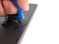
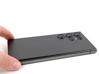
Apply a suction handle to the back cover, as close to the center of the right edge as possible.
-
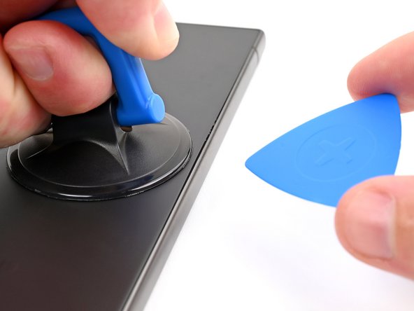
Pull up on the suction handle with strong, steady force to create a gap between the cover and the frame.
-
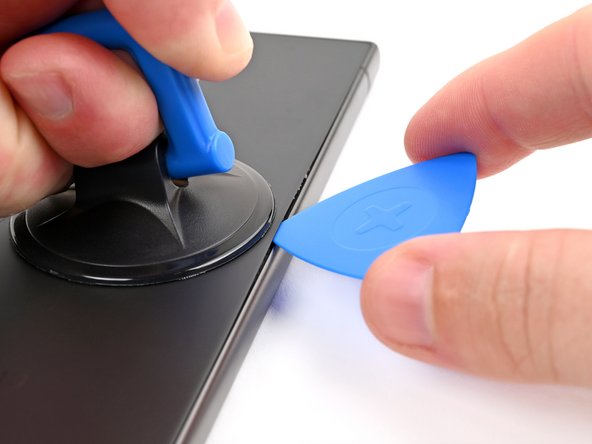
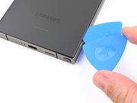
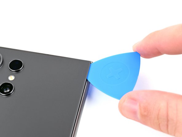
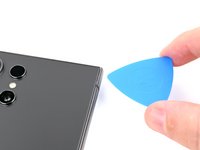
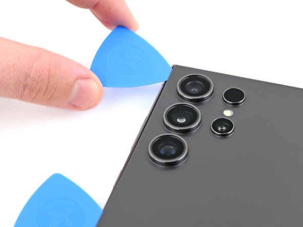
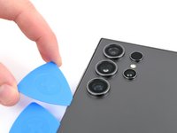
Insert an opening pick into the gap.
-
-
-
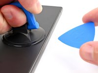
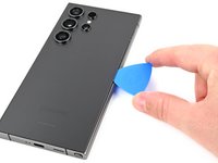
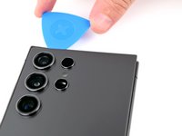
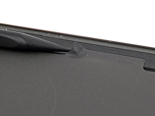
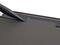
Slide the pick back and forth along the right edge to separate the adhesive.
-
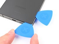
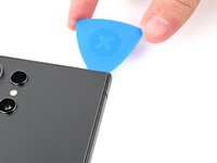
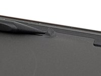
Leave the pick inserted near the bottom right corner to prevent the adhesive from resealing.
-
-
-
Apply a heated iOpener to the bottom edge of the back cover for two minutes.
-
-
-
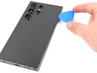
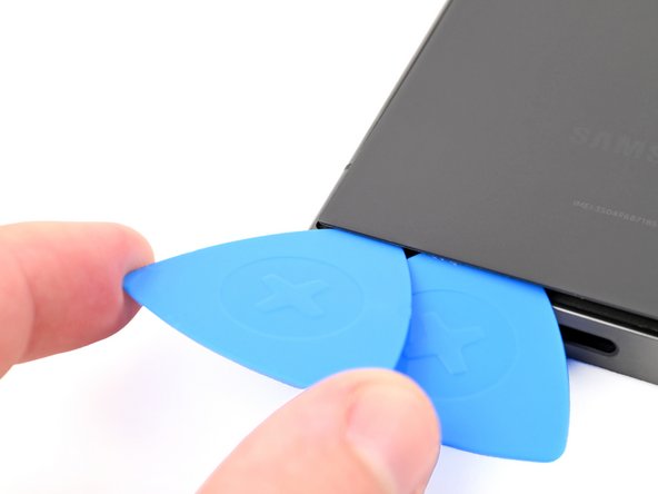
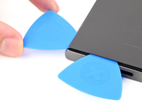
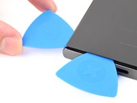
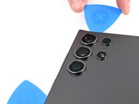
Insert a second opening pick next to the first one, near the bottom of the right edge.
-
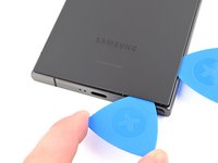
Rotate the opening pick around the bottom right corner to separate the adhesive.
-
-
-
Apply a heated iOpener to the left edge of the back cover for two minutes.
-
-
-
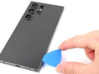
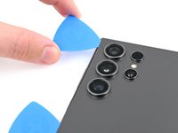
Insert a third opening pick next to the second one, near the left side of the bottom edge.
-
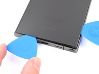
Rotate the opening pick around the bottom left corner to separate the adhesive.
-
-
-
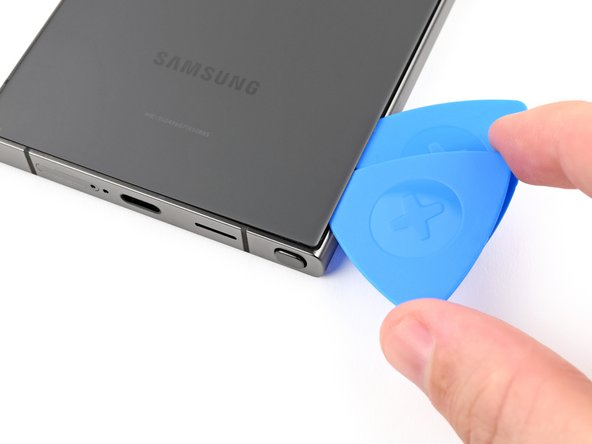
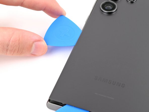
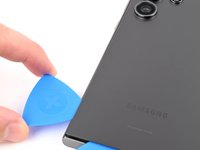
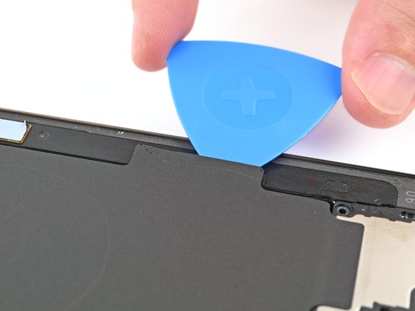
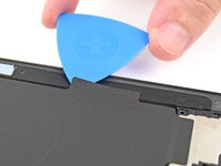
Insert an opening pick in the gap at the top of the right edge.
-
Rotate the opening pick around the top right corner to separate the adhesive.
-
-
-
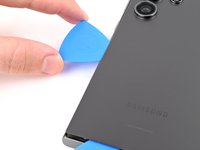
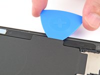
Slide the pick around the top left corner and down the left edge to separate the remaining adhesive.
-
-
-
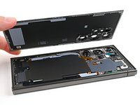
Grab and remove the back cover.
-
Remove any adhesive chunks with a pair of tweezers or your fingers. Apply heat if you're having trouble separating the adhesive.
-
If you're using custom-cut adhesives, follow this guide.
-
If you're using double-sided tape, follow this guide.
-
-
-
Use a spudger to pry up and disconnect the wireless charging coil press connector from the motherboard.
-
-
-
-
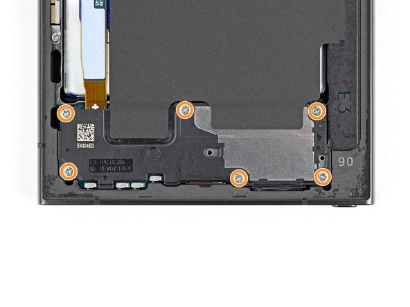
Use a Phillips screwdriver to remove the ten 3.5 mm‑long screws securing the wireless charging coil and the loudspeaker:
-
Four screws securing the wireless charging coil
-
Six screws securing the loudspeaker
-
-
-
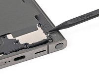
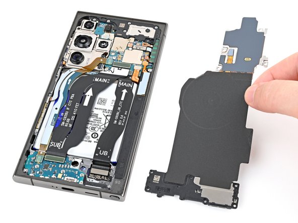
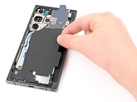
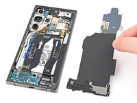
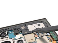
Use a spudger to gently pry up a corner of the tab of the wireless charging coil that's adhered to the right edge of the frame.
-
-
-
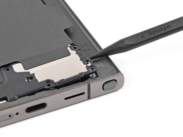
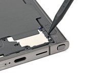
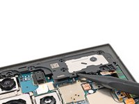
Insert the point of a spudger into the gap between the right edge of the loudspeaker and the frame.
-
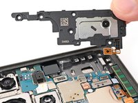
Pry up to unclip the loudspeaker from the frame.
-
-
-
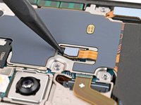
Use a spudger to pry up and disconnect the earpiece speaker press connector.
-
-
-
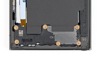
Use a Phillips screwdriver to remove the five 3.5 mm‑long screws securing the earpiece speaker.
-
-
-
Insert the pointed end of a spudger under the bottom edge of the earpiece speaker, under the engraved arrow.
-
Pry up with the spudger to unclip the speaker and remove it.
-
-
-
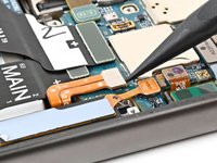
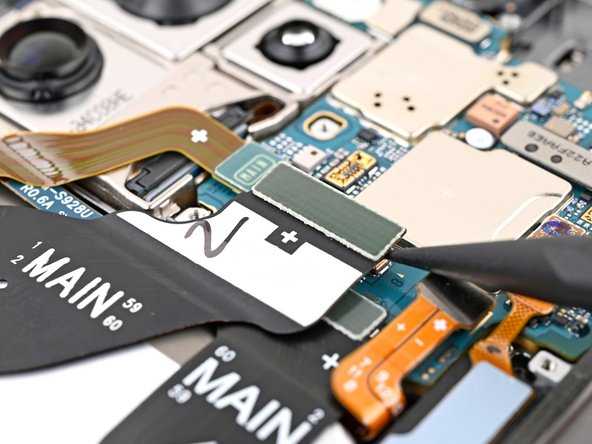
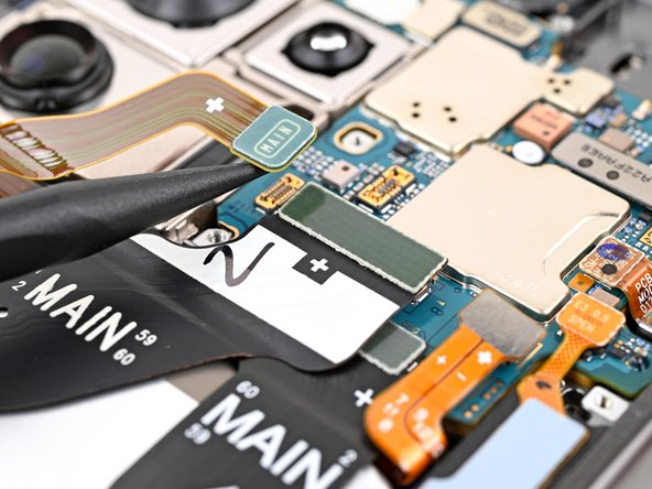
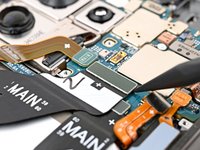
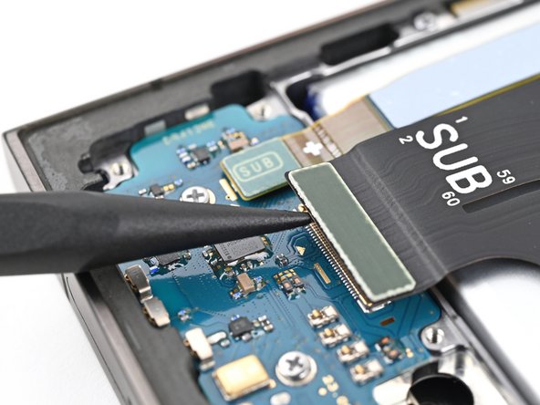
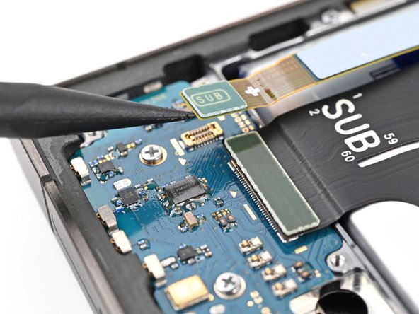
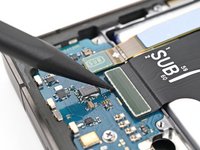
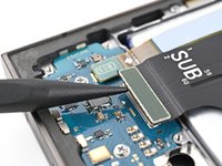
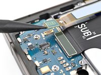
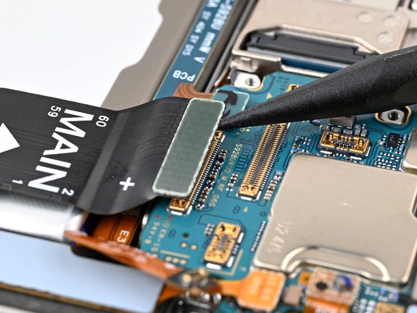
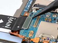
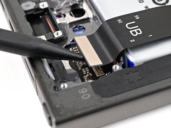
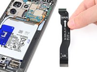
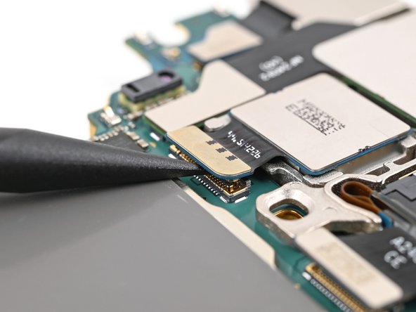
Use a spudger to pry up and disconnect both interconnect cable press connectors from the motherboard.
-
-
-
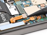
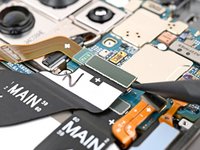
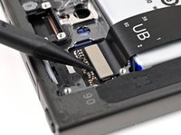
Use a spudger to pry up and disconnect the display cable press connector from the motherboard.
-
-
-
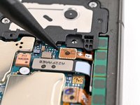
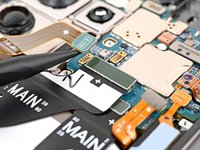
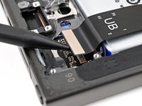
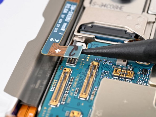
Use a spudger to pry up and disconnect the lower antenna press connector from the motherboard.
-
-
-
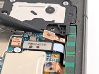
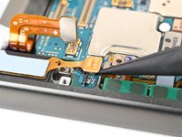
Use a spudger to pry up and disconnect the stylus port press connector from the motherboard.
-
-
-
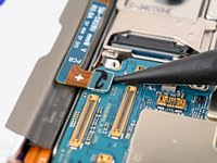
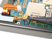
Use a spudger to pry up and disconnect the upper antenna press connector from the motherboard.
-
-
-
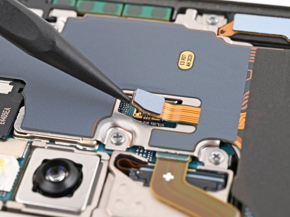
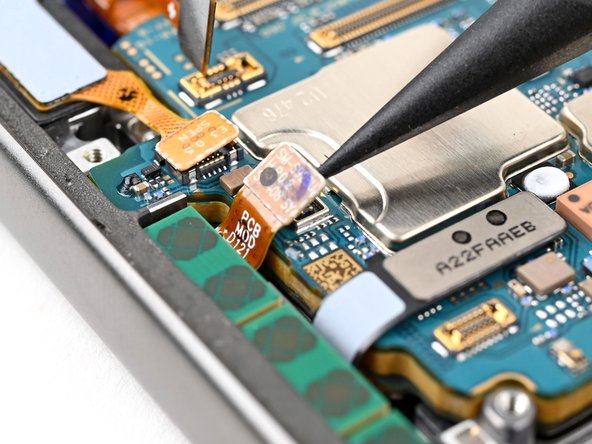
Use a spudger to pry up and disconnect the fingerprint scanner press connector from the motherboard.
-
-
-
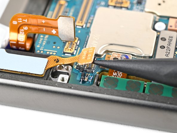
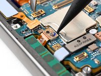
Use a spudger to pry up and disconnect the front camera press connector from the motherboard.
-
-
-
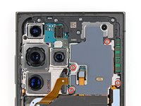
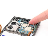
Use a Phillips screwdriver to remove the two screws securing the motherboard:
-
One 4.0 mm-long screw to the left of the top camera.
-
One 3.5 mm-long screw to the left of the bottom camera.
-
-
-
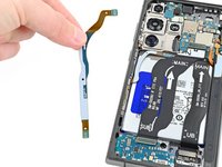
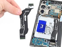
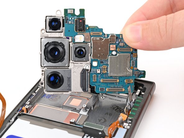
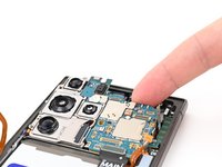
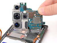
Use your finger or a spudger to lift the top of the motherboard.
-
Remove the motherboard.
-
-
-
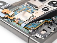
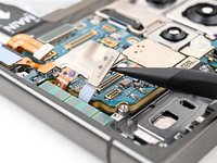
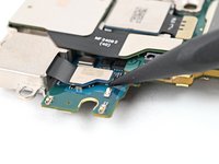
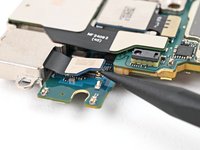
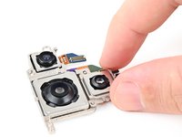
Flip over the motherboard to expose the rear camera press connectors.
-
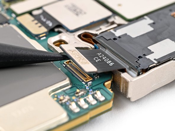
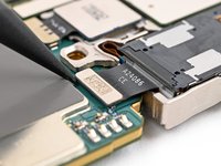
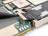
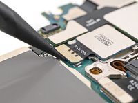
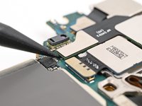
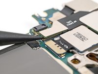
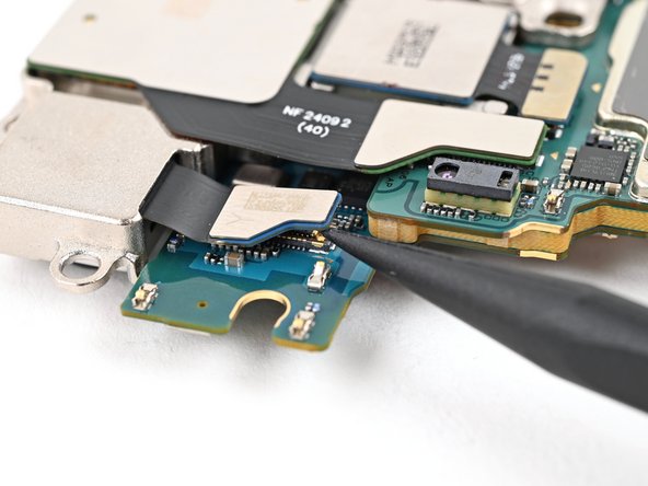
Use a spudger to pry up and disconnect the primary telephoto camera press connector.
-
-
-
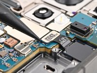
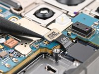
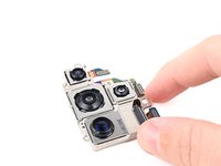
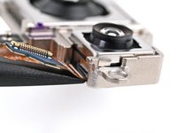
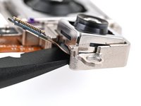
Use a Phillips screwdriver to remove the 3.5 mm‑long screw securing the cameras to the camera assembly housing.
-
-
-
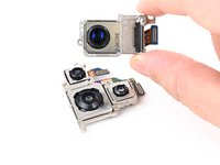
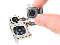
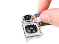
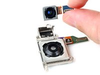
Flip the cameras over so the lenses are facing up.
-
Lift and remove the primary telephoto camera from the camera assembly housing.
-


To reassemble your device, follow these instructions in reverse order.
Repair didn’t go as planned? Try some basic troubleshooting, or ask our Answers community for help.
Take your e-waste to an R2 or e-Stewards certified recycler.
To reassemble your device, follow these instructions in reverse order.
Repair didn’t go as planned? Try some basic troubleshooting, or ask our Answers community for help.
Take your e-waste to an R2 or e-Stewards certified recycler.
ある他の人がこのガイドを完成しました。


コメント 1 件
I'm still waiting for you guys to sell the oem main camera sensor 🥲