はじめに
この修理ガイドはiFixitのスタッフによって作成されたものであり、Googleによって承認されたものではありません。修理ガイドの詳細はこちらを参照してください。
このガイドを使って充電アセンブリを交換しましょう。充電アセンブリにはUSB-Cポートが含まれ、振動モーターに接続しています。
必要な工具と部品
-
-
吸盤カップをしっかりと一定の圧力で引き上げて、フロントパネルとリアケースの間に開口ピックを差し込みます。
-
1.5mmより深くにピックを差し込まないでください。OLEDパネルを破損してしまうことがあります。
They cannot emphasize enough how careful you need to be when separating the screen. The iOpener does not work well enough to prevent breakage (opinion). I spent a majority of the hour and forty five minutes replacing my battery on removing the screen, i.e. reheating the iOpener, warming the device, slowly, with multiple passes, separating the adhesive. Use a heat gun or blow dryer.
try the alcohol as instructed instead of heat. “Do not heat your phone. If needed, you can use a dropper or syringe to inject isopropyl alcohol (90+%) around the edges of the back cover to weaken the adhesive. “
Rogerio Sa - 返信
Make sure to remove the adhesive under the top and bottom speakers to make it much easier to remove the screen.
Isopropyl alcohol works well to loosen the adhesive. However - GO SLOW. Slide the pick a bit, then apply some isopropyl alcohol into the gap where you’re sliding toward. Wait a moment, then slide a bit more. Move very slowly, particularly around the corners!
Any idea on what to do when the suction cup pops off of the screen before there’s enough clearance to slide the pick in?
I used a hairdryer to weaken the adhesive. If you place your finger in the path of the hairdryer you’ll have a good idea of when too much heat has been applied (when your skin becomes unhappy at the temperature). BE VERY GENTLE. I cracked my screen because I didn’t weaken the adhesive enough. I also chipped(dog eared) the corner of the OLED screen underneath with one of the plastic tools. Don’t stick it in too far. As the guide says, use the flat edge or the pick to help control this.
I did the 90% alcohol and the iOpener. Took a while but finally got the screen off. As others have mentioned, there is lots of adhesive around the top and bottom speaker openings. I ended up reaching in with a small brush and more alcohol to get it. I used a tooth pick to break the final adhesive.
I also had a set of dental tools and a set of magnifying goggles (I’m a model railroader) which helped greatly.
Like others have said, THIS STEP IS THE MOST DANGEROUS!!! You must be extremely gentle (no real force should be necessary to separate the screen from the glue) with the screen and take your time. (IMO if it takes you less than 30 mins to get the screen loose, your going too hard at it). Two suggestions from my successful battery replacement that I can give, use alcohol instead of heat (seems to work better with this phone) and start with a much thinner plastic tool that is also flexible (I used a metro card from the NYC MTA). This will allow you to get at the tiny gap without using any significant force and then get some alcohol into the gap by dripping it down the thin plastic tool. Honestly, IFIXIT should make a small thin rectangular card to use for this with lines around it for measurements…
The first pry to get the pick inside the edge of the screen needs A LOT OF HEAT and a very firm pull, and just as someone else mentioned, the iOpener did not work well, instead, a regular hair dryer proved more beneficial in applying a controlled amount of heat until its almost too hot to touch. Then, once the pick is inside 99% isopropyl alcohol worked wonders, use a syringe or dropper to apple some at the edge, wait for about 15 seconds and move the pick centimetre by centimetre. Make sure to not insert it more than 2mm at the sides. I took more than an hour just to get the screen off.
As an experienced (1) screen remover, I’d recommend that if you don’t plan to change your screen, change your plans. You will be less disappointed that way. I managed to get mine for just over $10 with shipping and test it first (weak Battery). Pixel 3’s (Not 3a or XL) sure look a lot better now. They have removable backs. My pixel 1st gen was a cheap lesson. Looking for another cheap one to try alcohol on.
Used a hairdryer on medium heat (very warm but not burning hot), suction cup, and applied isopropyl alcohol into crack made when applying pressure. Rinse and repeat until loosened enough to get a pick in. Took many attempts. Don't try to force the pick in, as you could chip the edge of the thin glass of screen this way. The suction cup pressure and weakened adhesive should do the work. Once the pick gets it, you can work a little faster but did the same basic steps minus needing the suction cup anymore, working around the edges. Good lighting is a must to see the crack forming.
Arthur Kay - 返信
I have to disagree with folks who said this is the longest step of the whole process...for me...the longest step was having to drive around and find a T4 Torx bit because this kit came with a T2 Torx which proved absolutely USELESS...
The screen came off very easily with the liberal application of 90% Isopropyl Alcohol. Took around 15min to get the screen off and I hardly had to use picks except for the top and bottom.
That Torx bit though... F$%^ED ME
-
-
-
デバイス下側の端に9mm以上差し込まないでください。ピックがOLEDパネルの折りたたんである部分に接触してしまうと、ディスプレイにダメージを与えてしまいます。
-
上部左側コーナーのエリアは浅く切開するだけで十分です。深くこじ開けてしまうと、フロントカメラにダメージを与えてしまいます。
This is inaccurate. The Pixel 2 phone’s back comes in two parts: a plastic main section and a glass back upper section. Only the glass section is required to be removed to replace the camera. Once the glass back is removed, the camera can easily be replaced without removing the motherboard, battery, or any other components. What is picture here looks like the original Google Pixel Phone.
Firstly, I disagree with hunter’s comment above - my Pixel 2 looked identical to this when I had it opened up.
Secondly, the whole thing about 1.5mm at the sides - literally scared the cr*p out of me when I started this as it’s such a tiny margin - but what this doesn’t say is that you can see these limits on your phone - just turn the screen on and it’s where the display ends - the digitiser starts there and is a couple of mm deep - hence the need to be careful. You can also see it (though less obviously) when you have the screen off - the jet black part at the edge is where the adhesive is - just make sure you don’t push in past there. It’s not like you can’t make very gentle contact with the digitiser when clearing the adhesive - I believe it’s just any kind of real pressure which will render the screen useless.
Dave Watts - 返信
I think it would be helpful to highlight the adhesive patches around the microphone/speaker areas and that you do need to project your pick in quite a distance to break this adhesive. I think simply creating a highlighted tracing of all of the adhesive areas would be helpful and pretty simple to do. It is shown to some extent, but in my opinion it could be more clear. In all of the prefaced concerns for digging too deep, I spent extra time and effort carefully prying upward and cracked my screen and OLED rendering my phone useless. Eventually I decided to probe more deeply toward the mic/speaker and broke things loose which allowed me to remove the screen easily.
Yes your right. I didn't e that and I disassembly the scree from it's digitiser layer. If i would know in advanced the adhesive borders it wouldn't happened.
I took my time but a few times I slipped in more than I wanted. No harm. The bottom is the more tricky. The adhesive around the bottom opening goes right up against the ribbon cable for the screen. I got the edges unglued with alcohol & iOpener. I then gently pried the screen away and reached in with a small brush and more alcohol. I then used a toothpick to break the last pieces of adhesive.
Besides the adhesive at the edges, there are 2 rectangular shaped adhesive patches at the top (around the speaker) and bottom (around the microphone). These are pretty thick, but can be easily chipped away with the pick. You start to see these as you gently lift the screen upwards with the suction cup and peer inside (use a flashlight). I did not need to use a heat gun or blow dryer. Just the pick and some isopropyl alcohol.
Use isopropyl alcohol with a syringe at the top and bottom speaker to weaken the adhesive, gently pull apart (about 2mm) and use a finer piece of plastic (like a milky file plastic sheet) to cut through the adhesive at the speakers, but still do not take the screen off completely yet! After extensively reading about failed attempts to get the screen off (instances where people damaged the OLED underneath) one thing is in common: few devices have little adhesive underneath the ribbon cable as well, which people failed to notice and while separating the screen and in turn, damaged the OLED because of the pull from the ribbon cable. Thanks to having this information beforehand I found the same issue in my phone after I separated the screen (not completely) from the frame, I used a piece of finer sheet of plastic to cut the adhesive holding the ribbon cable. You will have to be extremely patient and take your time.
i spent probably 3 hours on this step only last night, incredibly difficult. turned out that the OLED itself was glued to the midframe which made it extra hard (and ended up breaking the screen in the process. I did buy the phone refurbished so I don't think they are all glued this way but it is definitely worth knowing.
Using 91% isopropyl alcohol worked way better than applying heat. Was applying heat for 20 minutes with no luck to get the initial opening. IPA did the job in 2 minutes. I would be cautious with how much alcohol you are dropping. Do not be too generous as some have mentioned and just drop along the edges at incremental distances. The alcohol will dissolve the grey foam in the picture with X marks and flatten it. Not that big of a deal but if you are picky about not damaging anything in the process you should be careful about it.
-
-
-
デバイス上部端にピックを再挿入して、ディスプレイを慎重にこじ開けます。
This for me was by far the hardest step. What this guide fails to say is just how much adhesive you’ll encounter - mine was heaving with the stuff - so I wouldn’t attempt this fix without the rubbing alcohol, and I would be prepared to spend 30 mins on this - the images above make it look like as soon as you can get the pick in and around the whole phone the display will come off - this wasn’t true on mine, and I put a small crack in the top of my screen as I applied a little pressure to lever the top - the edges were ok, but there was so much adhesive at the top and bottom - right down and around the speaker grills - that I used scissors to cut the remaining strands as I managed to lift the screen higher enough! Don’t be shy with the rubbing alcohol, it really helps - and you really need to feel all sides loosen properly before you attempt to lever - but if you’re patient, it’ll be ok.
Dave Watts - 返信
agree, way more adhesive at top and bottom than guide implies. go really slow on sides with thin plastic but top and bottom speaker needs a bigger dig
-
-
-
画像のように、リアケース上部上にディスプレイを慎重に載せます。ディスプレイのリボンケーブルが切断したり、折り目が入らないようにご注意ください。
-
ディスプレイケーブルのブラケットを固定している4.0 mm T5トルクスネジを2本外します。
I cannot imagine how much easier this project would be if they provided the bit for this screw and the others of the same size. The torx bit included in my kit is a 2mm - entirely useless here. Only other bits are Philips...also pretty useless...
-
-
-
-
スパッジャーの先端を使って、ディスプレイケーブルコネクタを跳ね上げて、マザーボード上のソケットから外します。
Wow, I think I damaged my motherboard on this step. It would be helpful if there was a warning in this step to avoid doing that! Now my pixel 2 is reduced to a cool paperweight with a static display.
Yep, there’s a small surface mounted component below the connector that is super easy to dislodge from the circuit board. Shown in this YouTube video - https://www.youtube.com/watch?v=0BEpgqpI.... Unfortunately, the part is smaller than a grain of sand, so not really practical for the average fixer to put back on the board.
jlyonsmith - 返信
A spudger is the wrong tool to remove the video connector. You cannot see where you are poking with that tool and I wound up dislodging one of the surface mounted devices hidden by the connector and ruining the phone. I also broke a ground path near the corner of the middle frame that is not mentioned in this repair procedure. Watch this YouTube before you begin disassembly: https://www.youtube.com/watch?v=yKULr67Z...
None of the tools provided in the repair kit seemed slim enough to fit the space required to pry this up. I ended up using a thin / flimsy plastic health care card to get under and pry up. It popped up with enough pressure.
Arthur Kay - 返信
-
-
-
温めたiOpenerを、ミッドフレーム上部端の近接センサ上に約2分間載せて、接着剤を柔らかくします。
-
-
-
スパッジャーの先端を近接センサーケーブルの下に差し込んで、正面カメラに一番近い側のケーブルからスライドします。
-
慎重にセンサーがミッドフレームに対して垂直になるまで、ケーブルの端を持ち上げます。
This piece is actually glued down - heat and rubbing alcohol really helped as at first I couldn’t figure out why I couldn’t get it to move.
Dave Watts - 返信
-
-
-
イヤホンスピーカー下のネジを覆っているテープの一部分を剥がします。他のネジを覆っているテープも同様に剥がします。
-
ミッドフレームを固定している次のネジを外します。
-
3.7 mm #00プラスネジー11本
-
4 mm T5トルクスネジー1本
On my Pixel 2, I also had to peel back a small strip of conductive tape that was directly above (and the same kind as) the “screw below the earpiece speaker” mentioned above. It appears to be a ground strap to the assembly underneath.
Me too! Please change the photo?
If you don't peel the mesh tape up, it will year. I'm not sure if it plays into the screen potentially not working, but it seems to be a ground for the midframe and the display ribbon has a ground contact to the
Many of the screws would not come out due to the original threadlocker on the threads. I found that if I just kept moving them around with a toothpick, I could get the out. I also had one of those telescoping magnetic bolt grabbers that pulled the screws out.
Would be nice if they included the correct torx bit in the tool kit... mine came with a T2 Torx...pretty useless...managed to get the display ribbon cable free as those screws were surprisingly not super tight - got them with the included Philips bit...pretty F$%^ED right here
@JensDavidsen, I'm sorry to hear that the kit came with the wrong bit. We do everything we can to make sure that our tool kits are kitted correctly. I've gone ahead and forwarded your information over to CS so they can get this fixed for you. In the future, if you have any questions or concerns, don't hesitate to reach out to us directly.
You will also need to peel up the grounding tape below the front camera from the right. Be careful about not being too aggressive else you might lose adhesion while putting it back. I used some glue to ensure it would stick again during reassembly.
What kind of glue did you use? I suspect that a) it could change the contact of the ribbon, therefore hindering conductivity and b) that the glue might change over time, e.g. break down and cause side-effects.
arne -
-
-
-
開口ツールをホールドボタン付近のミッドフレームの溝に差し込みます。
-
ミッドフレームとデバイスケースの間に隙間が生じるまで、ミッドフレームを持ち上げます。ミッドフレームをまだ完全に外さないでください。
This is to pop a securing tab out it's place
On re-assembly make sure the securing tab, near the notch you use to open it, is inserted back under the frame again - this caused me to have to re-open my phone as my screen didn’t sit back down properly after I had put everything back together.
Dave Watts - 返信
It is more effort than I anticipated. I really thought I was going to break it, but it was fine.
-
-
-
下側端からミッドフレームを持ち上げます。
-
ミッドフレームが、デバイス本体に対して45度持ち上がったら、まっすぐデバイスから引き抜きます。
-
ミッドフレームを持ち上げたら、ミッドフレームの小さなスロットから近接センサを慎重に差し抜いてください。
While not shown here in the photo, there is a short braided cable between the midframe and the motherboard near the front facing camera that prevents separating the midframe completely (ground?). Be careful not to damage this cable when completing the remaining steps or carefully remove before trying to separate the midframe completely.
ericdowens - 返信
As ericdowens says above, there’s a small silver sliver of a connector (next to the front-facing camera). The guides on youtube said it was a grounding wire. This guide doesn’t mention it. Mine broke when I removed the midframe. No big deal. I stuck it back down with some tape when I put it all back together. Phone works fine.
I had a heck of a time levering up the midframe. I had popped the side with the opening tool, but the other side was really stuck. I used some alcohol along the edge thinking there was some adhesive. Not sure. I eventually used a dental pick to pop it loose.
And when reinstalling, don’t forget to move the short braided cable back out of the way so you don’t trap it inside.
STOP! Before you lift the midframe, the ground strap mentioned by ericdowens and Alex Lawson definitely will break if you don’t remove it from the midframe before lifting. I didn’t quite know what they were talking about, so thought I’d look for it as I was lifting the midframe, as I was sure if I was careful I’d spot it before it would break. I was very gentle, and I still broke it before realising what they were talking about. Look for some silver mesh tape on the midframe, near the forward-facing camera, same kind of tape as over the screw shown in Step 14. I’m going to try and carefully tape mine back together as Alex Lawson did, but it will be very fiddly, wish I hadn’t broken it in the first place!
Jamie Lamb - 返信
I broke mine... then proceeded to pilfer about 2mm worth of the tape depicted in step 18 because it's a silvery adhesive.
-
-
-
スパッジャーの平面側先端を使って、バッテリーコネクタの接続を外します。
This photo and tutorial doesn't show the shielding on the chips of the motherboard. And the glue…My pixel 2 had the volume button ribbon cable glued to the shielding. Carefully pry the cable off. Very carefully slide under it. Maybe use a little heat to soften the glue. You cannot just remove the motherboard with removing the ribbon cable for the volume buttons.
-
-
-
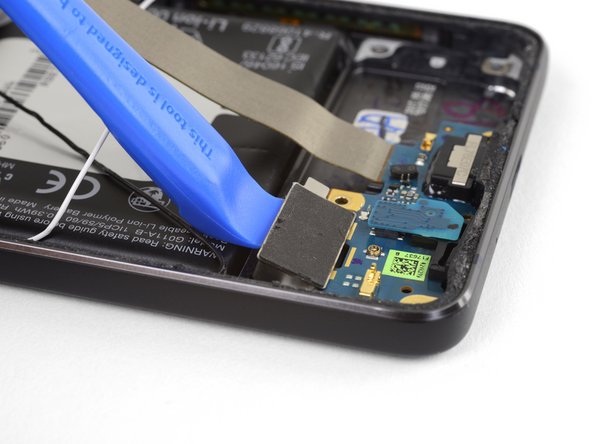
スパッジャーの平面側先端を使って、充電アセンブリコネクタの接続を外します。
There is a metal cover not shown here that covers the motherboard, on it the charging assembly is glued with a little adhesive. To remove it apply heat with the iOpener or a heat gun and carefully pull it with an spudger or a tweezer.
-
-
-
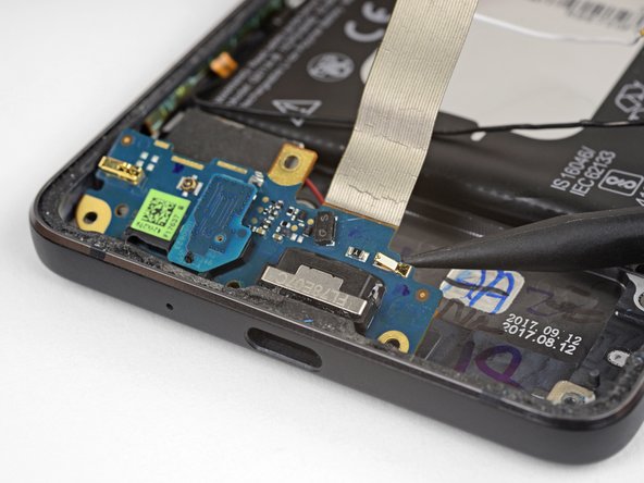
スパッジャーの先端を使って、ソケットから水平にスピーカーケーブルのコネクタ両側を少しずつ交互に押し出します。
This step is correct but does not explain the design of the socket or the process needed to remove it very well. The two wires enter a socket that has a very thin (you will need a magnifier to see it well) edge. This is what is pulled out horizontally from the circuit board socket. The socket base remains on the board. It would be 2000% helpful if there was a photo showing a close-up of the socket base from the socket itself - together in the same photo. The good news is if you are replacing the charging port, the new board will have a socket base into which you can plug your socket.
-
-
-
振動モーターがデバイスに接着剤で固定されていないことを確認してください。それから充電アセンブリを慎重にデバイスから持ち上げて、同時にモーターを取り出します。
-
マイクロフォンボードを取り外し、新しい充電アセンブリに移します。
In the last step, the microphone board is attached to the charging assembly and needs to be removed and placed on the new assembly when replacing.
I wish I could highlight your comment or get the original author to point this out in an image. I didn’t check this the first time through and had to pull the phone back apart to add the mic onto the new charging assembly.
(My mistake for not checking the boards against each other carefully - all other instructions were so thorough, I didn’t feel the need at the time to verify.)
-


交換用のパーツとオリジナルのパーツを見比べてください。残りのコンポーネントを移植する必要があるか、パーツを装着する前に接着剤の裏張りを取る必要があります。
デバイスを再組み立てする際は、これらの手順を逆の順番に従って作業を進めてください。
e-wasteを処理する場合は、認可済みリサイクルセンターR2を通じて廃棄してください。
修理が上手く進みませんか?トラブルシュートのヘルプには、アンサーコミュニティを参照してください。
交換用のパーツとオリジナルのパーツを見比べてください。残りのコンポーネントを移植する必要があるか、パーツを装着する前に接着剤の裏張りを取る必要があります。
デバイスを再組み立てする際は、これらの手順を逆の順番に従って作業を進めてください。
e-wasteを処理する場合は、認可済みリサイクルセンターR2を通じて廃棄してください。
修理が上手く進みませんか?トラブルシュートのヘルプには、アンサーコミュニティを参照してください。
14 の人々がこのガイドを完成させました。
以下の翻訳者の皆さんにお礼を申し上げます:
100%

これらの翻訳者の方々は世界を修理する私たちのサポートをしてくれています。 あなたも貢献してみませんか?
翻訳を始める ›

3 件のコメント
I’m fairly disappointed with this. It didn’t say that the microphone chip had to be transferred to a new part. This caused me to take this phone apart twice.
Is the charging assembly PCBA really responsible for battery charging?
Or is it just supplying the 5V from the charger thru the flex to the motherboard, which is in fact responsible for the charging?
There are additional "data" pins on the battery, which I suppose are also used during charging to report battery temperature etc., but these pins are not directly connected to the flex connector.
So I think that the motherboard is responsible for charging.
My phone is not charging, but i can measure the 5V from the USB on the motherboard connector at the end of the flex. Will it help to change the charging assembly?
My screen is severly cracked. I would recommend clear packaging tape as it is wide enough to accomodate the suction cup. Thinner cellophane tape won’t seal properly.
John Tippitt - 返信
Does the Google Pixel 2 have be powered off before removing the digitizer screen? Its not mentioned in this article...
Will the phone be damaged if the power is still on when disconnecting the broken screen?
Alex - 返信
Replacing the battery in my Pixel 2 was successful because I read the comments. They are invaluable in this endeavor.
David Castro - 返信
Suggest procedure revision:
Step 1: Read all steps and associated comments before proceeding.
Step 2: Ensure they supplied you with the right F$%^ING TOOLS in the kit before proceeding.
I'm F$%^ED because any store around me that might have this T4 Torx bit is already closed and my screen is already off. My kit came with a T2 Torx bit which is not used anywhere in this entire process.
Jens Davidsen - 返信
I bought one of the kits and it had everything needed to change the battery except the alcohol, including spudgers, screwdriver, torx (2 sizes), tweezer, alcohol dispenser, glue strips and die-cut glue card that fit the phone case perfectly. I followed these instructions and read the comments. Applied alcohol and patience, took my time and got the job done without any damage to the phone. Thank you ifixit!
Jeffrey Price - 返信