Center Chassis Removal (Power Supply Attached)

はじめに
手順 1 に進むThis guide shows how to removal the center chassis in your Xbox Series X. This guide has the power supply still attached, which reduces the amount of steps needed for a motherboard replacement or SSD removal.
必要な工具と部品
ツール


もっと見る
-
-
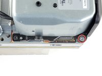
Use a pair of tweezers to remove the sticker hiding the first screw on the back panel, near the base.
-
-
この手順で使用する道具:Magnetic Project Mat$19.95
-
Use a T8 Torx driver to remove the two 7.4 mm‑long screws securing the back panel.
-
-
-
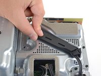
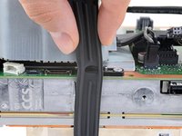
Insert the flat end of a spudger into the gap between the back panel and the shell, near the left side of the base.
-
Pry up the back panel to release it from the locking clips.
-
-
-
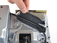
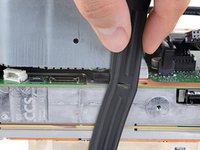
Grip the back panel at the opening you just created and pull it up and away from the shell to unclip the long edges.
-
-
-
Use a T8 Torx driver to remove the three screws securing the fan to the center chassis:
-
One 10.5 mm pancake screw
-
Two 8.8 mm screws
-
-
この手順で使用する道具:Tweezers$4.99
-
Use your fingers or a pair of blunt tweezers to grip the edges of the fan cable connector, and pull up to disconnect it from the center chassis.
-
-
-
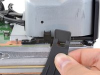
Use the flat end of a spudger to lift up on the locking tab holding the base to the shell.
-
-
-
Grip the base and rotate it counterclockwise to unlock it from the shell.
-
Remove the base.
-
-
-
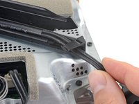
Use a T8 Torx driver to remove the two 8.8 mm screws securing the optical drive's vibration isolator to the shell: one on the base and one on the top of the isolator.
-
-
-
この手順で使用する道具:Tweezers$4.99
-
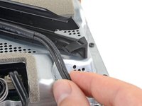
Use a pair of blunt tweezers to grip the edges of the optical drive power connector and pull up to disconnect it from the optical drive.
-
Use your fingers to pull up and disconnect the data cable from the optical drive.
-
-
-
Grip the top edge of the optical drive and pull it out of its slot in the shell to remove it.
-
-
-
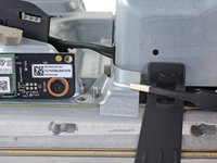
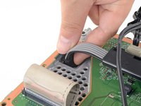
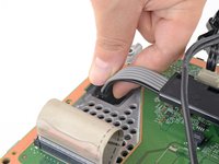
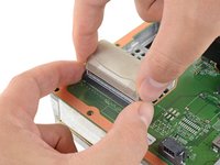
Use the flat end of a spudger to flip open the metal locking tab on the USB port ribbon cable.
-
-
-
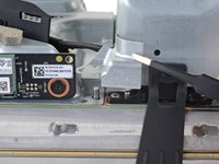
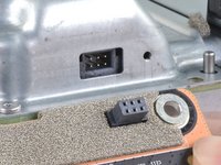
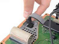
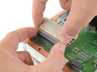
Use the pointed end of a spudger to depress the metal tab on the side of the power button cable's board connector.
-
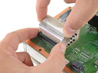
With the metal tab depressed, use a pair of tweezers to pull up on the pull tab to disconnect the power button cable from the center chassis.
-
-
-
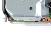
Use a T8 Torx driver to remove the three 7.4 mm screws securing the center chassis assembly to the shell.
-
-
-
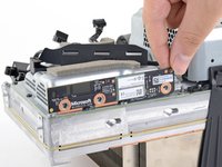
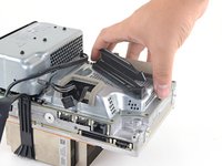
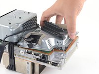
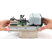
Grip the center chassis and pull it towards the green fan grille at the top of the shell, uncoupling the guide pegs from the shell.
-
Lift out the center chassis assembly to remove it from the shell.
-
-
-
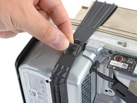
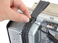
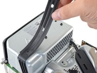
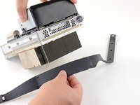
Unlatch the chassis strap from the right side of the power supply.
-
-
-
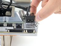
Use a T8 Torx driver to remove the three screws securing the power cable port to the chassis:
-
Two 13.1 mm screws
-
One 35 mm screw
-
-
-
Use a T8 Torx driver to remove the 8.8 mm screw securing the power supply corner cover.
-
-
-
Use a T8 Torx driver to remove the three 9.6 mm screws securing the accessory antenna board to the center chassis.
-
-
-
Use a T8 Torx driver to remove the nine screws securing the board shield:
-
Six 8.8 mm black screws
-
Two 35 mm silver screws
-
One 13.1 mm silver screw
-
-
-
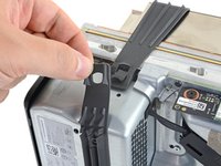
Disconnect the chassis strap from the locking tabs on either side of the power supply.
-
-
-
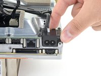
Grip and compress the locking tab on the 10-pin power connector.
-
While compressing the locking tab, lift the connector straight up to disconnect it from the board.
-
-
-
Use a T8 Torx driver to remove the three 35 mm‑long silver screws from the power supply—leave the fourth black screw in place.
-
-
-
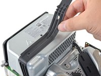
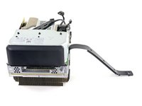
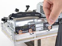
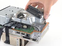
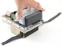
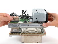
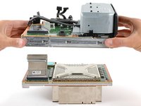
Grip the edges of the center chassis (not the power supply) and lift it off of the motherboard and heatsink assembly, routing the interconnect cable through its cutout.
-