はじめに
このガイドを参照して、Steam Deck LCD 右側ボタンボードを交換します。
一般的な静電気放電(ESD)の手順に従うことを忘れないでください。
この手順は、コンソールのボタンボードを物理的に取り外して交換する方法のみ説明しています。交換した基板が正しく機能するには、追加のソフトウェアツールおよびキャリブレーション作業が必要な場合があります。
必要な工具と部品
-
この手順で使用する道具:FixMat$36.95
-
プラスドライバーを使って、バックカバーを固定している8本のネジを外します。
-
長さ9.5mmの粗ネジー4本
-
長さ5.8mmネジー4本
there should be a picture of the SD card slot at the start of every Steam Deck teardown. i know the note is there but i generally use the pictures to guide me and forgetting to remove the SD card is a very critical step
I agree, I just broke mine...
What is the the #1 philips used for? Only the #0 is mentioned in the instructions.
I wish they would specify which size to use for which screws.
Mark D -
I found it easiest to use a PH1 for the red screws, and PH0 for the rest (including the internals.)
I used the PH1 bit for this. You can use smaller bits but ideally there should be no play of the bit in the screw head.
I used the PH1 for the 9.5mm screws and PH00 for the 5.8mm screws. The PH0 wanted to strip one of the small ones.
Pol Llovet - 返信
Just a point for knowledge sake, the Four 5.8mm screws on this step are factory installed with a version of locktite. Not sure why but there will be slight resistance when removing the first time.
The screw bit that came with my fix kit just stripped the screws of my steam deck. I guess I should've just sent it in...
Model 1030 SteamDeck uses Torque #6 (CR-V T6) 5.0mm for all 8 screws making it far less likely to damage the screw heads.
Model 1030 is the OLED version, which we have separate guides for! See here: Steam Deck OLED
-
-
-
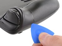
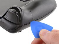
オープニングピックを右側グリップの端に沿って、バックカバーとフロントシェルの間に差し込みます。
-
バックカバーをこじ開けると、ロッキングクリップから外れます。
I found it easiest to start this process at the top of the device near the fan exit.
second that and inserting the pick in the bottom middle and sliding the pick to each side
Sub -
I also found the top near the fan exit to be easier
Thank you for this tip, it definitely was easy starting at the top instead of by the bumper/triggers. After I opened the top I did the bottom and then it was way easier to gently open the sides. be very careful and go slowly to make sure that none of the clips are damaged
Luis B -
this as suggested above:
1. open the top
2. open the bottom
3.gently open the sides
I also started from the middle of the deck and worked my way out since I couldn't get a grip with the pick on the deck's side grips. Since this is a common step for pretty much all guides for opening the deck I think it's also worth noting that you should be careful not to bend the trims/seams where the front and back covers meet with the pick. When I first opened my deck you can definitely see where I nudged the pick in between the covers since I was probably using too much force on the pick itself.
It would be useful to note here that if you want to insert the little blue triangular iFixit opening picks into the right side along the edge, there isn't actually a gap as the directions say, at least not on newer Decks. You'll be making the initial gap using the pick. Brace it on something because you will need to use enough downward force that you're flexing the pick a bit and it'll probably be digging into the skin of a bare hand. With enough force suddenly it will make a click and go in just a bit, and then you're in business.
plastic picks didnt work for me but finger males did the job on prying this open
This step was the hardest by far. First I didn't find an opening at the sides, and it did take a really long time until I finally got it open... Then, when I had the one side opening open it didn't just pop out, I needed to slide all the way to the other side with the pick and open everything. I guess they made it even more drop resistant.
-
-
-
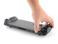
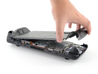
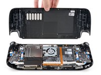
バックカバーの開口部を握り、本体から上へ引き離し、長い辺をクリップから外します。
-
バックカバーを取り出します。
If you have an SD card, you will want to take it out. I followed the guide and didn't think about the SD card I had inside. When I went to snap the case back on it clapped shut on the exposed SD card, shearing it in half and leaving the bottom half stuck in the SD card slot. I am still endeavoring to get it out.
you can use the case that comes with the steam deck to support it once the lid is removed
You can get the pry pick inserted easier if you start in the gap for the shoulder buttons. A lego brick separator works well here
-
-
この手順で使用する道具:Tweezers$4.99
-
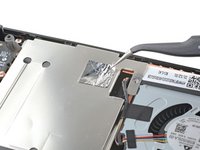
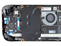
ピンセットを使って、ボードシールド上の隠れたネジを覆っているフォイルテープの一部分を剥がします。
Use some heat here from a hairdryer to make this part easier.
If you screw up here you can replace the little aluminium square with some aluminium tape from Amazon. No less than 50 microns thick, slightly thicker is fine. and the square is 13mm both ways.
Thanks for that Matt, i destroyed the original tape and i had no solution since i read your comment.
You should not. This is EM shielding to protect your processor and ram from radio waves in the air
I found out my 3 Weeks new Steam Deck is a old Version... gg. Valve...
wenn ich aluminium foile benutze, womit soll ich sie dann verkleben?
If we have the new version with the black shield, how do we access the SSD?
I need this part, does anyone know where to get it?
-
-
-
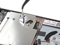
プラスドライバーを使って、ボードシールドを固定している3本のネジを外します。
-
3.4mmネジー1本
-
3.7mmネジー2本
The procedure ended here for me, used an ifixit PH 00 bit on the screw behind the aluminium tape, bit wouldnt bite too great, one wrong twist and the screw was stripped. Not sure who or what initially screwed in that particular screw as the rest of the screws on the shield were fine, but boy is it in there tight. So now i have a stripped screw and a botched ssd replacement, don't think valve will let me RMA for this, but i'll give it a try and update accordingly.
Any updates? Did they let you RMA?
I found one screw to be ridiculously tight too, managed to undo it without stripping thanks to reading your comment beforehand and going extra careful. Not going to lie, it was a tense moment :D
Andy HL -
I'm stuck in the same place. I haven't fully stripped it, but I can tell you that if I try and make it budge it will strip. The thing is massively overtightened. The driver fit fine, the metal just gives way before the screw will budge.
I think the tendency is to go too small on the screwdriver bits because you're working on small electronics.
I used the PH1 bit on the screw under the foil and the PH0 bit for the two remaining screws without any problems.
What does this shield actually do? Some kind of magnetic protection?
if I had to replace the key (R2) and that's it, can I directly remove it or do I have to act here on the motherboard too?
have you gotten an answer yet? trying to change mines as well but dont wanna do too much to the deck
briaNN -
button Not key, i’m sorry
FYI there is a little pin on the cover that slots into the board. It is located near the top screw. I needed that to be inserted for the cover to go back down properly.
For anyone who may have stripped a 3.7mm screw, Steam Support states it's M1.6 diameter with a 0.35 thread pitch and a 3mm length. Hopefully that'll help anyone trying to locate a replacement screw. Hoping iFixIt can make an internal screws kit as they're kinda hard to find the right one online.
Did valve change the shield recently as my new 64gb deck has a black shield with no hidden screw.
Yes there's a new hardware revision out there that some people are getting. Consider stopping at this point and putting your deck back together if you have one of these new hardware revisions (the fan is quite different as well to the pictures) until iFixit has an updated repair guide.
Simon M. -
There are only 2 screws now, but be careful taking the shield off, because there are still thermal pads under it sticking it to a heat pipe.
I need this piece, can someone help me where can I find it please?
Hi, is it possible to buy these shields somewhere? I am extremely interested in buying a replacement.
Yannick B. - 返信
Model 1030 is the OLED version, which we have separate guides for! See here: Steam Deck OLED
-
-
-
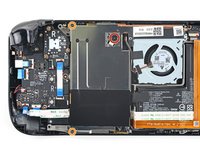
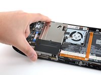
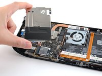
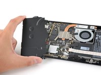
ボードシールドを外します。
During reassembly, ensure that the fan cable lays on the side of the board shield and isn't pinched underneath.
Are you saying that the fan cable should be positioned above the board shield instead of being pressed down by it? Just like the image shows, where it 'lays on the side of the board shield'?
Necesito esta pieza la mía no la traía se ve que se la quitaro
-
-
-
-
バッテリーケーブルのプルタブを持ち、マザーボードから直接引き離して、切断します。
After fully reassembling my device I found that my battery was not showing any stats anymore. I couldn't start the device without being plugged in, however if I restarted it would stay on even if my power cable was detached. Battery showed 0%. It turns out I had not fully reinserted the battery cable at this stage during reassembly. MAKE SURE YOU PUSH IT ALL THE WAY BACK IN!
Awesome thanks for this tip!
It is helpful to lift up gently with a the tapered end of a spudger underneath the tucked-in portion of the battery cable, creating a bit of flex in the cable before pulling on the pull tab. I found that without doing so, the fabric pull-tab simply tore off of the cable under light-to-moderate force (the fabric itself ripped cleanly across, like a paper towel). Careful, gentle pressure with a spudger can be used to remove the plug by prying gently on the rear ridge of the plastic plug (not the wire!) if this happens.
This is exactly what happened to me. Maybe it was a pull tab previously, mine was a ribbon cable that tore - captured the image here: https://www.ianwootten.co.uk/2022/11/22/...
This was the best approach (and I feel safest for the wiring) for me. Mostly push pressure on the plastic ridge with some minor pull tension on the fabric.
Victor -
I found it less scary and easier to remove the battery connection by using a fingernail on the ridge and pushing it off the connector. I felt like pulling on the battery cable was too harsh.
Yeah, pulling cables like these is usually ill advice. They might be fine if it's a new device, but for old devices that have been sitting there for years, there's a good chance the connector has grown brittle and the cable might just come off separately (something I learnt the hard way).
skzm -
I second this approach. For me, the cable felt way to flimsy and the connector wouldn't budge even under moderate force. Except I used the flat end of a spudger to "scrape" it out.
Misza -
Upon plugging the battery back in, I found it easy to use two spudgers- one on each side- to pull/push the connector back into it's port. Be careful to not put any pressure on the battery wires themselves.
When reconnecting the battery cable, you'll know when it's inserted and power is restored, because the white LED will illuminate at the top of the Deck near the power button. You should be able to see it while you're reconnecting the battery cable
This is only true if you haven't put the deck into battery storage mode as directed.
Why not just let the battery discharge completely and then not have to disconnect it?
Completely discharging a battery reduces its lifespan. It's completely unnecessary.
Because no lipo battery is ever completely discharged -- you would not be able to recharge it if it was. There will always be enough power left in it to cause damage if shorted even if it isn't charged enough to power up the device it's connected to.
I would personally not recommend pulling the tab. It doesn’t apply force at the correct angle. You should revise these instructions to advise using a combination of pulling on the tab, and careful pressure on the connector towards the right of the mainboard to carefully work it out.
Using the pull tab alone could cause problems if not done extremely carefully.
This part was wayyyyy easier than I anticipated and I worried for nothing because I used the ifixit spudger to push it out a bit and then I literally used my finger nail and was able to slide it right off. Dont be afraid, its not that difficult and its not that delicate to break if you do it patiently
I inserted the cable very firmly with a spunger, being careful not to press down too hard on the cables, and even tried redoing it, but I don't see any LED illumination. I am now unable to boot the deck into the boot manager. Any additional tips?
What is the risk of not unplugging the battery? Just curious!
Nick Hight - 返信
Once I was changing termal paste on my Windows based expensive tablet PC... And I was so scared to disconnect any cables (there was many of them), so I did it all with battery connected (I didn't even knew where is battery cable). When I tried to put board shield back... it didn't go right into needed place... and short circuit some small component. It flashed. That was the end of my repair. Dudies from repair service later told me that multiple components fried including CPU, so repairing is too hard. That's what can happen if you don't disconnect battery.
To pull the battery out I used my spunger, but the batter had actually not space to be pulled out completely. I needed to lift the cable up with the spunger to get the cable fully out. When plugging it in again I had to press the battery down kinda hard so it would fit again. This was really scary and I recommand using two spunger as someone said above.
Does it have to be a clean fingernail?
I disagree with the order here: I think the battery should be disconnected right after step 4. You can do that before touching anything else by gently pulling the pull tab to the right.
If all you want to do is to disconnect and reconnect your battery (because your Steam Deck is not booting up... again...) then with a bit of finesse, luck and a flat plastic tool you can even push it back in without removing the shield. Make sure it went all the way back in.
-
-
-
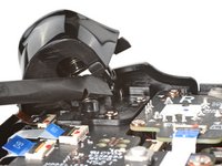
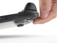
トリガーの右クリップの内側の端に、スパッジャーの平らな先端を当てます。
-
トリガークリップをペグから離し、上に回して、ラッチを解除します。
This is unnecessary on the revised Model 1030 if you only need to access the Quick Access button. Jump to Step 13.
Model 1030 is the OLED version, which we have separate guides for! See here: Steam Deck OLED
-
-
-
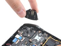
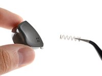
右側のトリガーを外します。
In case the spring gets lost, it's 19 mm long with about 14 coils.
Thank you this is helpful
reconbot -
When putting this back on be sure to note the instructions for reassembly above. Catch the outer peg, align the inner one, and push. Having a flashlight on the inner peg helped me get it lined up.
-
-
-
右側のトリガーブラケットを外します。
The right bumper button on my switch deck stopped working after the deck was accidentally dropped from 5ft. When I got to this step of the instructions, I was able to see that the momentary switch that the button triggers had been bent backwards from the impact, making it difficult for the button to trigger the switch. I bent the switch back to its original position, which fixed the mechanical problem. Unfortunately the solder joints for the switch cracked when I pressed the switch forward. I re-flowed the solder joints with a tiny Weber iron that I filed down to a narrow point. The button works properly now.
-
-
この手順で使用する道具:Tweezers$4.99
-
-
プラスドライバーを使って、サムスティックを固定している5.2mmネジを3本外します。
This is unnecessary if you only need to access the Quick Access button on the revised Model 1030. Jump to step 16.
Model 1030 is the OLED version, which we have separate guides for! See here: Steam Deck OLED
-
-
-
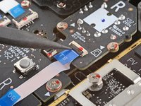
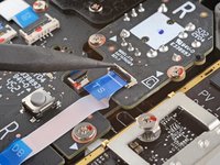
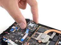
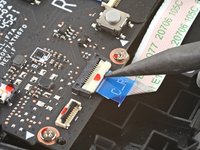
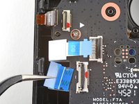
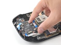
スパッジャーの先端を使って、ボタンボードケーブルのZIFコネクタ上の小さなロッキングフラップを跳ね上げます。
-
ピンセットを使って、コネクタからケーブルをスライドして外します。
-
-
-
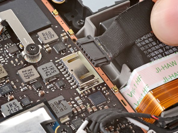
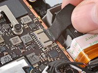
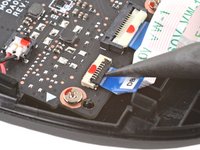
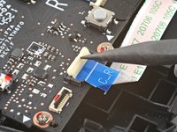
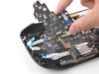
スパッジャーの片側先端を使って、ボタンボードの相互接続ケーブルのZIFコネクタ上にある、小さなロッキングフラップを跳ね上げます。
-
ピンセットを使って、コネクタからケーブルをスライドして外します。
Be very mindful of this cable during re-assembly, if this cable isn't fully seated properly the deck will turn on slowly and not be able to recognize any inputs besides the touch screen.
Hmm, I wonder if this is my problem. I replaced my case with the Clear JSAUX one. Everything went fairly well, until I closed it up and noticed none of my buttons worked anymore. By "seated properly", how do you tell? When I look at it, it looks the same as the picture, with the white line showing
Eric, flip up the white locking flap and remove the cable. Then reinsert the cable — it should go in smoothly with no resistance, hence its name (ZIF = "Zero Insertion Force") — if you feel resistance, there might be something blocking the cable or its connection. If it slides in smoothly, make sure it bottoms out evenly and isn't at an odd angle. If everything looks good, your problem is probably elsewhere.
-
-
-
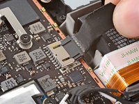
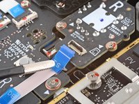
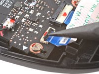
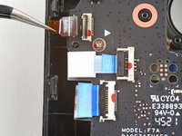
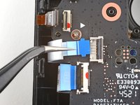
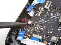
いずれかのコネクタがテープで覆われている場合は、ピンセットで剥がしてください。
-
スパッジャーの先端部分を使い、残りのボタンボードのZIFコネクタにある小さなロッキングフラップを持ち上げてください。ピンセットを使って、ケーブルをコネクタから滑り出させます。
-
アクションボタンケーブルの接続を外します。
-
タッチパッドボードケーブルの接続を外します。
-
タッチパッドケーブルの接続を外します。
-
-
-
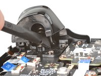
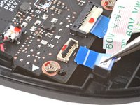
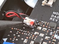
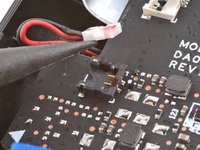
スパッジャーの先端を使って、ハプティックケーブルを持ち上げて接続を外します。
-
コネクタを外す代わりに、ハプティックをボタンボードに接続したままボタンボードを筐体の外側にひっくり返すことで作業の邪魔にならないようにすることもできます。
Personally, i think this should just be a suggested step, since the connector is different and requires more force to disconnect than the ribbon cable connectors and you can leave this connected and lay the board over to the side without disconnecting this and still access the buttons.
I agree with Peter on this. I tried fixing my right bumper before ordering a replacement and during disassembly I followed these instructions exactly and still broke the bracket that holds the haptics connector. Luckily my haptics seem to still be working after putting it back together but I have a feeling it will disconnect on its own after some time and I will be needing a whole new button board.
I did this very carefully and the bracket still broke
I broke the down part of the bracket as well. Glued it back on with some crazy glue applied with a wooden toothpick (to make sure to not touch anything else). Haptics still working. Next time I don't think I'll remove that connector.
I agree with everyone above. Attempting to disconnect the haptics is not worth it as it breaks extremely easily
Please remove this step. It is virtually impossible to remove this without breaking the housing and it's ultimately not necessary.
Wish I had seen this beforehand. My right connector just broke off. Ughhh.
Can this just be soldered back on or do I need a new button board? Because I have looked online and they seem impossible to find.
-
-
-
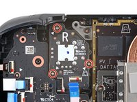
プラスドライバーを使って、右側ボタンボードを固定している4本のネジを外します。
-
5.2mmネジー3本
-
3.9 mmネジー1本
Once again, for the revised Model 1030, all of these screws are T6 of varying sizes, nothing like the original. Use your favourite way of keeping track of where to return the screws in their correct holes.
Model 1030 is the OLED version, which we have separate guides for! See here: Steam Deck OLED
-


このデバイスを再組み立てするには、インストラクションを逆の順番に従って作業を進めてください。
電子廃棄物(e-waste)は 適切な方法で処分してください。
修理が上手く進みませんか?ベーシックなトラブルシューティングを行うか、 Steam Deckのアンサーコミュニティに尋ねてみましょう。
このデバイスを再組み立てするには、インストラクションを逆の順番に従って作業を進めてください。
電子廃棄物(e-waste)は 適切な方法で処分してください。
修理が上手く進みませんか?ベーシックなトラブルシューティングを行うか、 Steam Deckのアンサーコミュニティに尋ねてみましょう。
6 の人々がこのガイドを完成させました。
以下の翻訳者の皆さんにお礼を申し上げます:
100%

これらの翻訳者の方々は世界を修理する私たちのサポートをしてくれています。 あなたも貢献してみませんか?
翻訳を始める ›


42 件のコメント
When will this part be available?
Is there any update to when this part will be available?
Tim Ceesay - 返信
Is there any estimated time to when this part will become available?
David Chan - 返信
Parroting everyone else. When will this part be available?
Yes, I need this part, as well. The plastic bumper piece is fine... the button on the board itself is my issue with my R1 button. Need this part... but don't want to send my Steam Deck away for several weeks on warranty... would rather fix it myself.
I fixed the micro switch myself, see my comment: Steam Deck 右側ボタンボードの交換
Shane Qi -
Same issue, it just came loose of the solder for me. Seems to take alot of the force of button press.
Michael -
I finally broke my screen (kid stepped on it next to my bed!) and I was going to buy both this part and a screen from iFixit and do the repairs myself.
This part isn't available! I guess I'll try and send it on warranty.
Man, I have an issue with my right R1 bumper. & they want me to send it in for that, @ NO CHARGE that's great & all but I STILL DONT TRUST THE SYSTEMS in place to protect my device I just can't see it being worth it in the long run scares TF outta me.
Don't get me wrong The Steam Deck is not that hard to obtain especially in the location I live. There are at least 5 Steam Decks being sold a day on Facebook Market Place. So, if it really came down to it I'd jus buy a new 1 while waitin for their idiot @%^!* to replace mines or figure out the issue/issue's. There is ALWAYS, I MEAN ALWAYS a dam issue when goin this route.
I hate being the negative Ned here, but its the dam truth. I have heard some of the narlyest Horror stories about people sending in for repairs to Valve on Redit. I know alot of the people posting on Redit are jus trolls but still if even 20% of the stories were true that's insane. & I jus don't care to deal with ANY of it, if I don't have too.
🎮👍-Best of luck to you buddy-👍🎮
What you mean you Finely broke your screen it's like you already predicted your Steam Dexks fate with bad JuJu.
LolLz did the Steamy Deck ever have a chance with an outlook like that?!? I don't think the Steam Deck REALLY ever had a chance . SADGE!!
Oh well as long as your able too fix her up I am happy! Haha. Also if your already gonna be buying a new screen I would suggest to upgrade too the newer anti glare screen it helps a WHOLE LOT MORE & if I am not mistaken the upgraded LCD is ONLY $99.99 WHICH IS SO WORTH IT!! Especially, if your already looking to replace the screen. Just some advice buddy. I mean other than that the "upgraded screen" wouldn't really be worth it. But in this case so worth it.
Same here daughter dropped my deck and right button ripped from the board would really like to replace the board ASAP
I fixed the micro switch myself, see my comment hope it helps: Steam Deck 右側ボタンボードの交換
Shane Qi -
When is this part going to be available to purchase? It's ridiculous that people have been asking the same question for months without any response at all
Jake Guest - 返信
Installing these boards in the Steam Deck requires special calibration that isn't currently publicly available. As of right now we don't know if/when these could be available for purchase.
If you are here because the L1/R1 micro switch is broken, you can replace just the micro switch. I've done it recently:
1. the micro switch I used was the sync/pair button of the Xbox controller, and it works just fine (iFixit sells the Xbox controller motherboard for $15 each)
2. later, I found the micro switch's model number: "TL3340AF160QG" (<$1 each)
3. I used a soldering iron to install it. It's not easy, but DIY-able. I have very little soldering experience, and I fixed it myself.
4. If you use hot air, don't blow directly on the plastic part of the micro switch because it could easily melt.
Here is the thread where I documented this project: https://mastodon.social/@shaneqi/1100088...
This only works if the solder pads don't rip off. I think a lot of us have broken pads and need alternate points of contact
@christianm74231 good point. In that case, we'd still need to wait for the board to be available, or RMA the deck.
Shane Qi -
I don’t suggest others do this, but this is what I did to “fix” my 512 GB deck:
All I had to do was buy a brand new 64 GB Steam Deck and I swapped DBs … The only problem (besides the fact that I had just paid $400 for a new Steam Deck when I only needed the DB) was that the L and R DB were connected by a different number of ribbon cables. My 512 GB Deck had one ribbon cable connecting the L and R DB together whereas the 64 GB Deck had two smaller ribbon cables, so I couldn’t just swap out the one side. Once I swapped both DBs and cables and put it all together, the shoulder buttons worked, but the trackpads could no longer detect pressure, so I couldn’t “click” with them. It wasn’t a huge loss though because I could still use Steam+LT/RT to perform mouse clicks.
Ewww, that's rough honestly seems like an extremely cringe time, AkA " Headache central. "
Hope the best buddy! Things will get better they always do maybe not as fast as we want them too but things WILL GET BETTER I promise!
I need THIS PART when will it be available as much trust as I have with Valve Inc. I STILL DONT TRUST ENOUGH TO SEND MY DEVICE FOR REPAIRS ESPECIALLY, when I can repair myself VERY EASLIY, especially since I am extremely electronically inclined THANK GOD! I couldn't imagine being dumb founded working on electronic devices like these.
A lot of Steam Decks are now past warranty. When will this part be available?
jeez.... also need same part.. this is a depressing comment thread.
I need a Right Button Board. When will it be available?
Bumping like every one else. Any updates on availability for the right daughter board? ZIF connector doesn't want to seat properly so I can no longer use the start button. All I need is the right-hand daughter board (Rev G for the 512GB).
ZW7,
Unfortunately, the Steam Deck button boards require Valve's special calibration software that still isn't publicly available. We still don't know if/when the boards could be available for purchase.
This is honestly really disappointing from Valve. Most Steam Decks are way past their warranty periods and this part should've been made available from day one! I know they have more important things to take care of but then why promise when you can't deliver? I'm hoping this will be made available soon.
Please make this available !
Is this part avalable yet? My R1 button have an issue missclicking alot.
if anyone is reading this, from what I've gathered from threads, Ifixit does not offer this part because it requires factory calibration that no one but valve has access to, so don't blame them for not offering the part. If your bumper switch is broken, and your solder pads are still intact, your best bet is to buy a replacement switch and solder it on yourself or find someone else to do it, that or pay the valve fine for them to fix your deck. It is truly tragic that this part is such a hassle, I know.
A placa não está disponível? Só as ferramentas?