はじめに
Follow this guide to replace the screen and battery assembly on your Samsung Galaxy S20 Ultra.
This guide is written for the screen and battery assembly. The assembly consists of the screen, battery, and frame together in one part. Be sure you have the right part before you begin the repair.
If your battery is swollen, take appropriate precautions. Before disassembling your device, completely discharge the battery. This reduces the risk of a dangerous thermal event if the battery is accidentally damaged during the repair.
Note: Retaining water resistance after the repair will depend on how well you reapply the adhesive, but your device will lose its IP (Ingress Protection) rating.
Some images in this guide may show minor discontinuities. They should not affect the overall guide procedure.
必要な工具と部品
-
-
Insert a SIM card eject tool, bit, or a straightened paperclip into the hole on the SIM tray, located at the top edge of the phone next to the plastic antenna band.
-
Press in firmly to eject the tray.
-
-
-
Heat an iOpener and apply it to the back cover's bottom edge for two minutes.
-
-
-
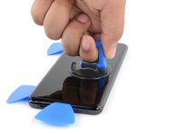
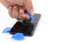
Apply a suction cup to the back of the phone, as close to the center of the bottom edge as possible.
-
Pull on the suction cup with strong, steady force to create a gap between the back cover and the frame.
-
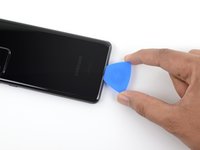
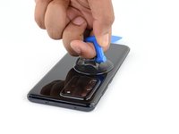
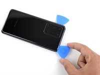
Insert the point of an opening pick into the gap.
-
-
-
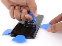
Slide the pick back and forth along the bottom edge to slice through the adhesive.
-
Leave your opening pick in the seam to prevent the adhesive from resealing.
-
-
-
Apply a heated iOpener to the left edge of the back cover for two minutes.
-
-
-
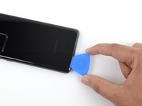
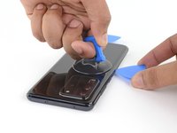
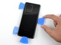
Apply a suction cup to the back of the phone, as close to the center of the left edge as possible.
-
Pull on the suction cup with strong, steady force to create a gap between the back cover and the frame.
-
Insert the point of an opening pick into the gap.
-
You can try also applying a few drops of high concentration (over 90%) isopropyl alcohol into the seam to help loosen the adhesive.
-
-
-
Apply a heated iOpener to the right edge of the back cover for two minutes.
-
-
-
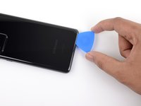
Apply a suction cup to the back of the phone, as close to the center of the right edge as possible.
-
Pull on the suction cup with strong, steady force to create a gap between the back cover and the frame.
-
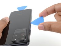
Insert the point of an opening pick into the gap.
-
-
-
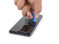
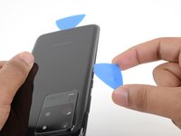
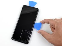
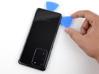
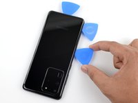
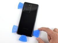
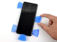
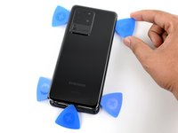
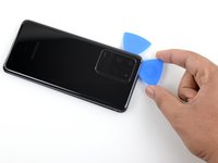
Gradually slide the pick from the right edge of the device around the top right corner.
-
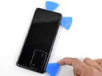
Continue slicing along the top edge to fully separate the back cover adhesive.
-
-
この手順で使用する道具:Tweezers$4.99
-
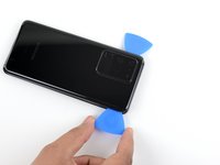
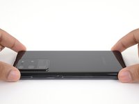
Lift the back cover slowly. Use opening picks to slice any remaining adhesive.
-
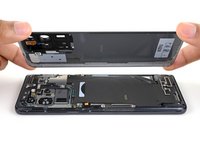
Remove the back cover.
-
This is a good point to power on your phone and test all functions before sealing it up.
-
Remove any adhesive chunks with a pair of tweezers or your fingers. Apply heat if you're having trouble separating the adhesive.
-
If you're using Samsung custom-cut adhesives, follow this guide.
-
If you're using double-sided tape, follow this guide.
-
-
-
-
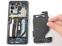
Use a spudger to pry up and disconnect the wireless charging coil connector.
-
-
この手順で使用する道具:Magnetic Project Mat$19.95
-
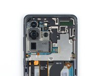
Use a Phillips #00 screwdriver to remove the five 3.9 mm-long screws securing the loudspeaker and lower midframe.
-
-
-
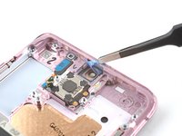
Insert the point of a spudger into the notch in the top left corner of the loudspeaker.
-
Pry up to release the clips holding it in place.
-
-
この手順で使用する道具:Tweezers$4.99
-
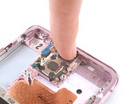
Use tweezers, or your fingers, to gently peel the wireless charging coil away from the device.
-
Remove the wireless charging coil.
-
-
-
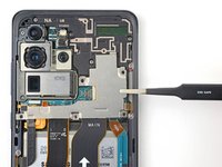
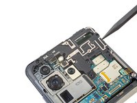
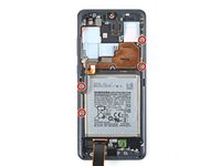
Use a Phillips #00 screwdriver to remove the five 3.9 mm-long screws securing the motherboard bracket.
-
-
この手順で使用する道具:Tweezers$4.99
-
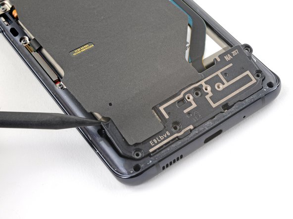
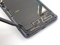
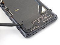
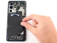
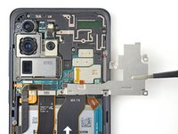
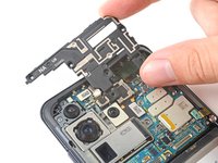
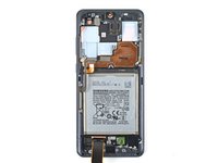
Use a pair of blunt-nose tweezers to unclip and remove the motherboard bracket.
-
-
-
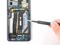
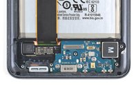
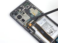
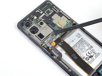
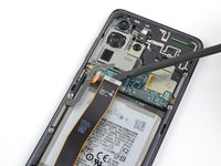
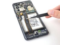
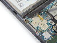
Use a spudger to pry up and disconnect the primary and secondary interconnect cables from the daughterboard near the bottom of the device.
-
-
-
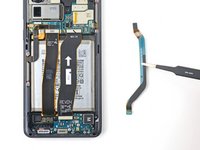
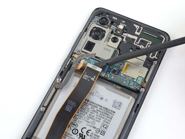
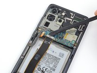
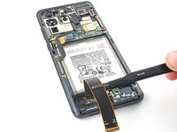
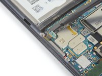
Use a spudger to pry up and disconnect the primary and secondary interconnect cables from the motherboard.
-
-
-
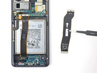
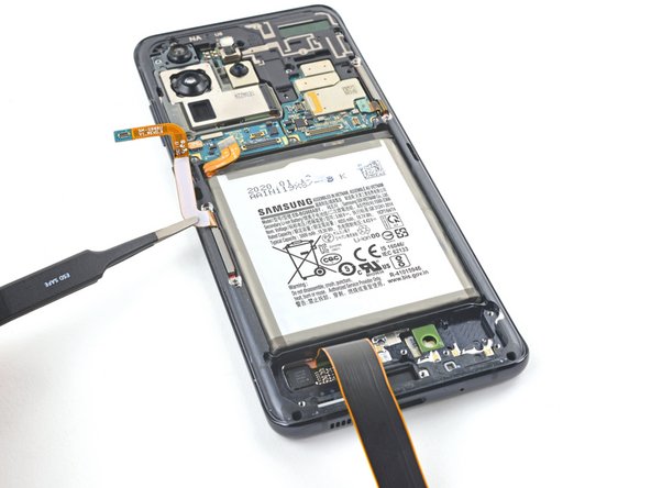
Gently peel up and remove the primary and secondary interconnect cables.
-
-
-
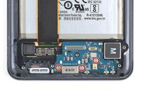
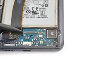
Use a Phillips #00 screwdriver to remove the three 3.7 mm-long screws securing the USB-C port and daughterboard.
-
-
-
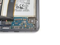
Insert the pointed end of a spudger under the left edge of the daughterboard and pry up to release it from its recess.
-
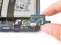
Use tweezers, or your fingers, to pull the daughterboard up and away from the bottom of the device and remove it.
-
-
-
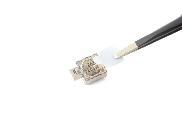
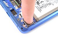
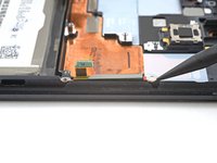
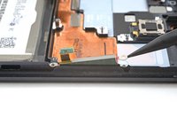
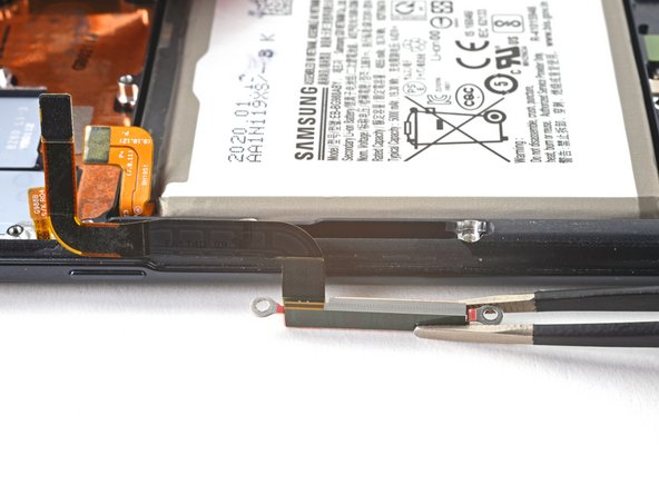
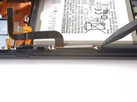
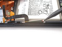
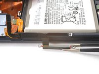
Insert the tip of a spudger between the frame and the notch in the vibrator's edge, close to the bottom edge of the device.
-
Pry up with the spudger to separate the vibrator from the frame.
-
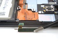
Remove the vibrator.
-
-
この手順で使用する道具:Tweezers$4.99
-
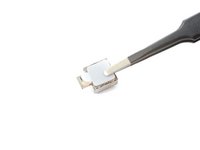
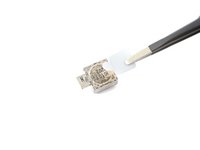
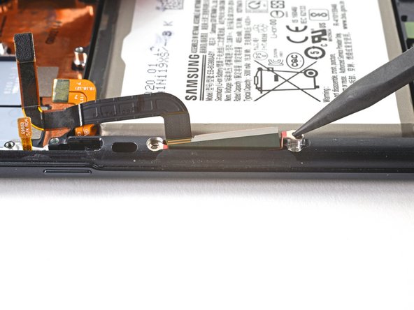
Peel off the vibrator adhesive from its liner and apply the sticky end to the bottom of the vibrator.
-
Use tweezers, or your fingers, to pull up on the white liner to expose the top layer of adhesive.
-
Insert the vibrator and apply pressure to adhere it to the frame.
-
-
-
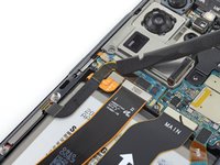
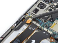
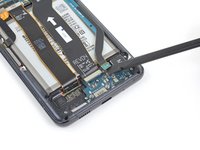
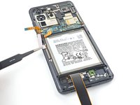
Pry up and disconnect the left 5G mmWave antenna connector from the motherboard.
-
-
-
Pry up and disconnect the display flex cable from the motherboard.
-
-
-
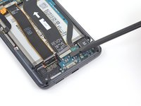
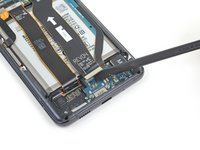
Gently peel up and bend the display and left 5G mmWave antenna flex cables out of the way of the motherboard and battery.
-
-
-
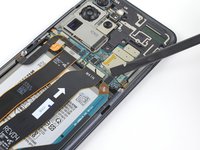
Use a Phillips #00 screwdriver to remove the four 3.9 mm-long screws securing the upper midframe.
-
-
-
Insert the point of a spudger into the notch on the right side of the upper midframe and pry up to release the clips holding it into place.
-
Remove the upper midframe.
-
-
-
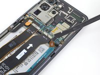
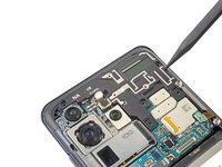
Pry up and disconnect the right 5G mmWave antenna flex cable from the motherboard.
-
Bend the cable out of the way of the motherboard.
-
-
-
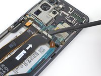
Pry up and disconnect the side button flex cable from the motherboard.
-
Bend the cable out of the way of the motherboard.
-
-
-
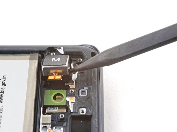
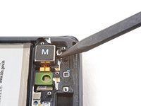
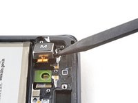
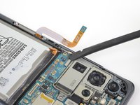
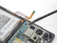
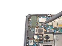
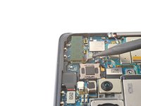
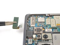
Pry up and disconnect the front camera flex cable from the motherboard.
-
Bend the cable out of the way of the motherboard.
-
-
-
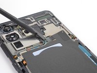
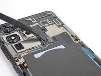
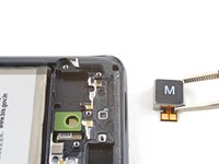
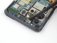
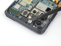
Pry up and disconnect the upper 5G mmWave antenna cable from the motherboard.
-
Use tweezers, or your fingers, to remove the upper 5G antenna.
-
-
-
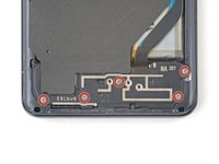
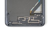
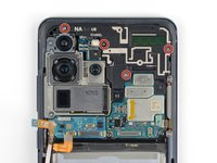
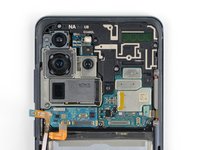
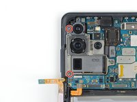
Use a Phillips #00 screwdriver to remove the two 3.9 mm-long screws securing the motherboard and camera assembly.
-
-
-
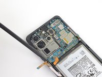
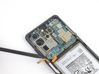
Insert the point of a spudger into the bottom left corner of the motherboard assembly and pry up to release it from the phone body.
-
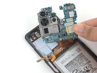
Remove the motherboard assembly.
-
-
-
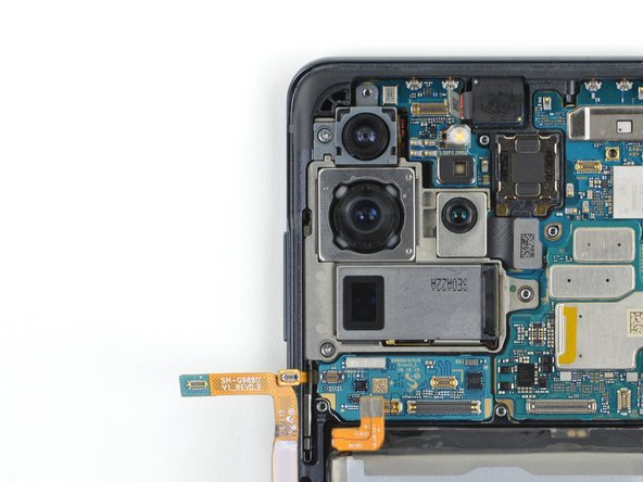
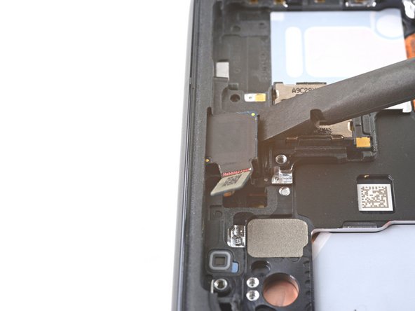
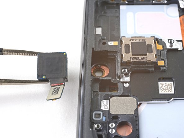
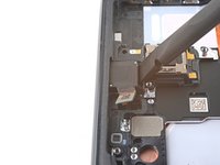
Insert a spudger into the gap between the frame and the front camera.
-
Pry up with the spudger to separate the front camera from the frame.
-
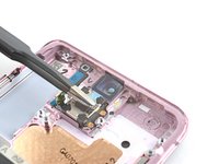
Use tweezers, or your fingers, to remove the front camera.
-
-
-
Peel off the front camera adhesive from its liner and apply the sticky end to the frame.
-
Use tweezers, or your fingers, to pull on the tab and expose the top layer of adhesive.
-
Insert the front camera and apply pressure to adhere it to the frame.
-
-
-
Use a Phillips screwdriver to remove the four 3.4 mm-long screws securing the 5G mmWave antennas.
-
-
-
Use the point of a spudger to pry up on the 5G mmWave antenna bracket's bottom screw tab.
-
Use tweezers, or your fingers, to remove the 5G mmWave antenna.
-
-
-
Use the point of a spudger to pry up on the 5G mmWave antenna bracket's top edge.
-
Use tweezers, or your fingers, to remove the 5G mmWave antenna.
-
-
-
You're now left with the screen and battery assembly.
-


To reassemble your device, follow these instructions in reverse order.
Take your e-waste to an R2 or e-Stewards certified recycler.
Repair didn’t go as planned? Try some basic troubleshooting, or ask our Answers community for help.
To reassemble your device, follow these instructions in reverse order.
Take your e-waste to an R2 or e-Stewards certified recycler.
Repair didn’t go as planned? Try some basic troubleshooting, or ask our Answers community for help.
11 の人々がこのガイドを完成させました。


コメント 1 件
Alex, thank you for the great instructions! They are very detailed and easy to follow. I followed them exactly and took my time. All went well. My phone works great again. I'm so happy to have it back in one piece and in like new condition! It took a little over 2 hours. Carl