はじめに
Use this guide to replace a worn-out or dead battery in a Microsoft Surface Pro 6.
For your safety, discharge the battery below 25% before disassembling your Surface. This reduces the risk of a dangerous thermal event if the battery is accidentally damaged during the repair.
If your battery is swollen, take appropriate precautions.
You'll need replacement adhesive for the battery in order to complete this repair. Strong double-sided tape like Tesa 61395 is recommended.
Applying new thermal paste to the CPU during reassembly may improve the performance of your Surface. If you wish to do that, make sure you have new thermal paste and either high-concentration isopropyl alcohol or a specialized thermal paste cleaner.
There is a significant chance that you may break the unreinforced and fragile display panel during this procedure. Be sure to apply plenty of heat and be extremely careful during the prying stage.
必要な工具と部品
-
-
If the screen's glass is cracked, keep further breakage contained and prevent bodily harm during your repair by taping over the glass. Lay overlapping strips of clear packing tape over the display until all the glass is covered. Wear safety glasses to protect your eyes.
-
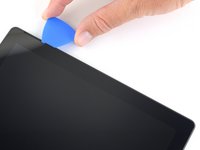
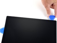
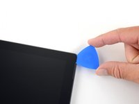
Heat an iOpener and apply it to the right edge of the Surface's screen for two minutes.
-
-
-
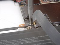
Take note of the screen adhesive layout before continuing:
-
These areas only contain adhesive and are safe to cut.
-
The display board and flex cables sit here close to the edge. Cut very carefully and do not insert the pick as deep under the display.
-
Fragile antenna cables lie under this part of the screen. Carefully follow the procedure to avoid damaging them. The adhesive is also the thickest here.
-
-
-
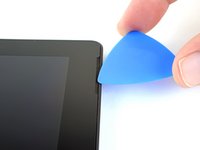
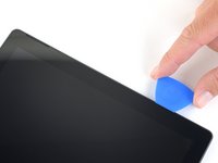
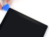
Insert an opening pick into the speaker opening on the screen and slide the pick under the glass. Do not press the pick into the speaker grille, as the grille is easily torn.
-
-
-
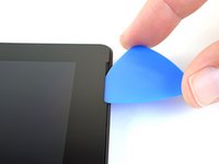
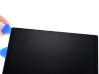
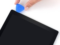
Rotate the pick toward the bottom of the Surface to slide it underneath the lower edge of the speaker cutout.
-
-
-
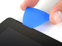
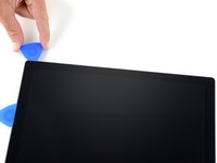
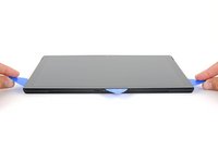
Slide the pick down the right edge of the Surface to slice through the adhesive under the screen.
-
Leave this opening pick in the right edge to prevent the adhesive from resealing.
-
-
-
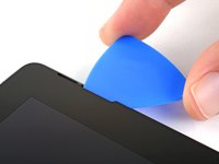
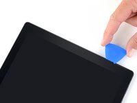
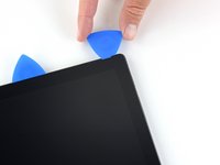
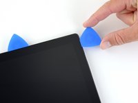
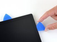
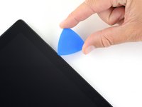
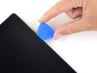
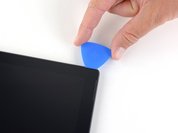
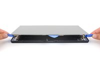
Insert the point of a pick under the display where you just stopped cutting. Do not insert the pick deeper than the edge of the bezel.
-
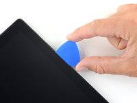
Carefully roll the pick to the right, pressing the long edge of the pick into the screen adhesive underneath the bezel, cutting the adhesive as you go. Do not slide the pick along the edge of the Surface.
-
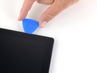
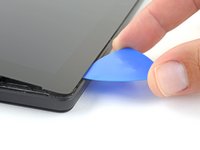
Repeat this motion of inserting the point of the pick where you just cut, and rolling to the right all along the top edge of the Surface, until the pick is 2.5 inches (64 mm) from the right edge of the Surface.
-
-
-
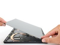
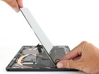
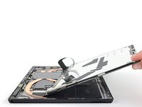
Very slowly lift the screen assembly away from the Surface case. If you encounter any resistance, stop and check that all the adhesive is separated.
-
Use an opening pick to cut through any remaining adhesive.
-
-
-
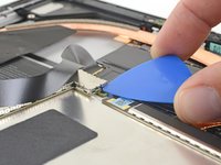
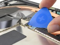
Use an opening pick to pry up one edge of the EMI shield covering the display board.
-
Repeat this procedure at different points around the shield until it is free.
-
-
この手順で使用する道具:Tweezers$4.99
-
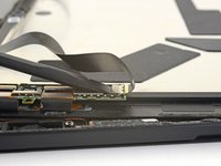
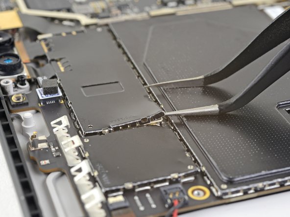
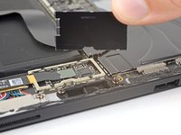
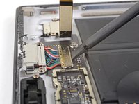
Insert one point of a pair of pointed tweezers into a gap in the edge of the EMI shield covering the digitizer connector.
-
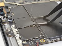
Use the tweezers to pry the EMI shield away from the display as much as you can without bending it.
-
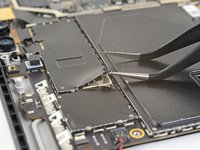
Repeat this procedure at different points around the shield until it is free. Remove the shield.
-
-
-
-
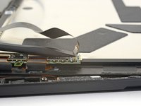
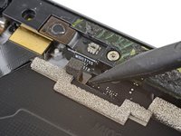
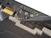
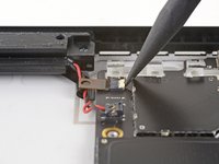
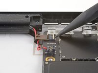
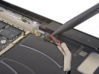
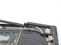
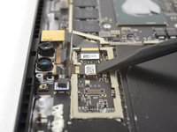
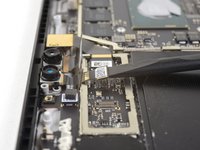
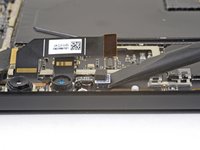
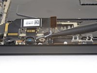
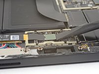
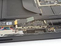
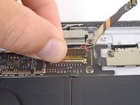
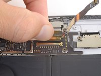
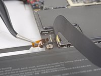
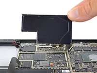
Use the point of a spudger to pry the microphone connector straight up and out of its socket on the motherboard.
-
-
-
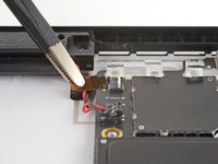
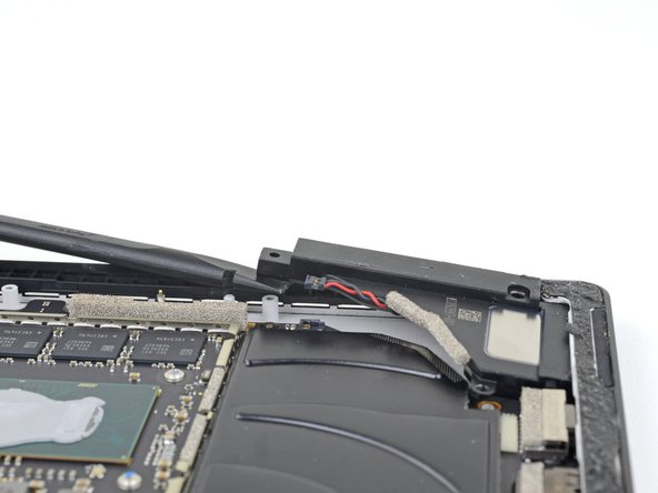
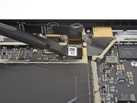
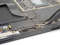
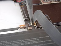
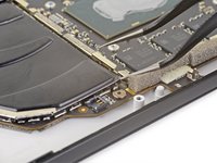
Use a T5 Torx driver to remove the four screws securing the antenna support:
-
Three 4.5 mm screws
-
One 6 mm screw
-
-
-
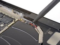
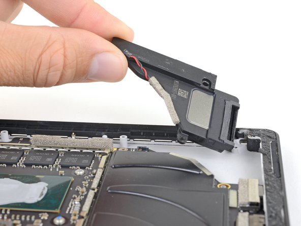
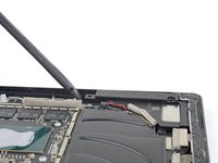
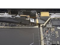
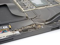
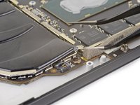
Use a spudger to lift the antenna support out of its recess in the Surface.
-
Remove the antenna support.
-
-
この手順で使用する道具:Tweezers$4.99
-
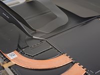
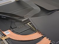
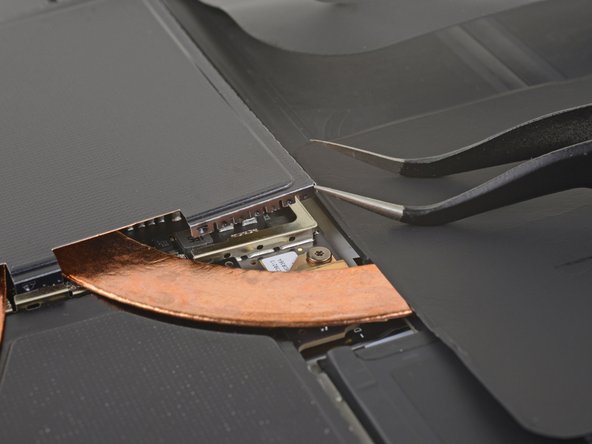
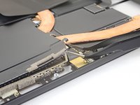
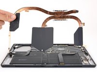
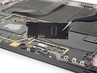
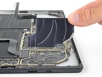
Insert one point of a pair of pointed tweezers into a gap in the corner of the EMI shield covering the heat sink.
-
Use the tweezers to pry the EMI shield away from the motherboard as much as you can without bending it. Do not remove it yet.
-
-
-
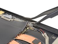
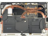
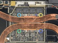
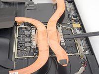
Remove the ten Torx screws securing the heat sink:
-
Six 2.6 mm-long T3 screws
-
Four 3.3 mm-long T5 screws
-
Screw 1
-
Screw 2
-
Screw 3
-
Screw 4
-
-
-
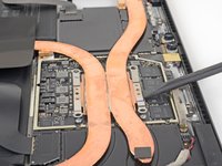
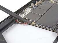
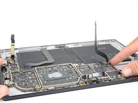
Use the point of a spudger to lift the left speaker connector out of its socket on the motherboard.
-
-
-
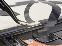
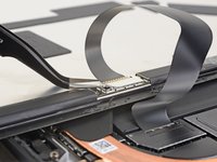
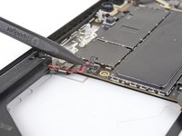
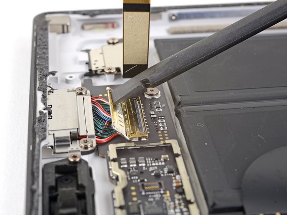
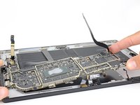
Use the point of a spudger to flip up the small locking flap securing the volume and power button cable ZIF connector.
-
Slide the volume and power button cable straight out of its socket on the motherboard.
-
-
-
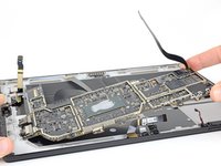
Use the point of a spudger to lift the right speaker connector out of its socket on the motherboard.
-
-
-
Use a T5 Torx driver to remove the two screws securing the right speaker:
-
One 6 mm screw
-
One 3.7 mm screw
-
-
-
Use a spudger to lift the left edge of the right speaker so that it clears the components around the speaker.
-
With the left edge lifted, slide the speaker to the left, straight out of its recess in the case.
-
-
この手順で使用する道具:Tweezers$4.99
-
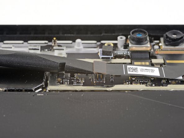
Insert one point of a pair of pointed tweezers into a gap in the corner of the EMI shield covering the camera connectors.
-
Use the tweezers to pry the EMI shield away from the motherboard as much as you can without bending it.
-
Repeat this procedure at different points around the shield until it is free. Remove the shield.
-
-
-
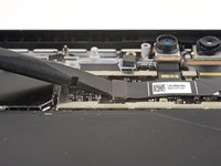
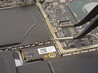
Use the flat end of a spudger to pry the front-facing camera connector up and out of its socket on the motherboard.
-
-
-
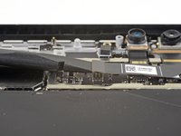
Use the flat end of a spudger to pry the rear-facing camera connector up and out of its socket on the motherboard.
-
-
-
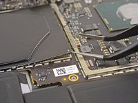
Use the flat end of a spudger to pry the microphone connector up and out of its socket on the motherboard.
-
-
-
Insert one point of a pair of pointed tweezers into a gap in the corner of the EMI shield covering the microSD card reader connector.
-
Use the tweezers to pry the EMI shield away from the motherboard as much as you can without bending it.
-
Repeat this procedure at different points around the shield until it is free. Remove the shield.
-
-
-
Use the flat end of a spudger to pry the microSD card reader connector up and out of its socket on the motherboard.
-
-
-
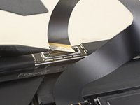
Use the flat end of a spudger to lift the flap that sits over the SurfaceConnect port connector.
-
-
-
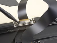
Use the point of a spudger to flip up the small locking flap securing the headphone jack cable ZIF connector.
-
Slide the headphone jack cable straight out of its socket on the motherboard.
-
-
-
Insert one point of a pair of pointed tweezers into a gap in the corner of the left-most of the remaining large EMI shields.
-
Use the tweezers to pry the EMI shield away from the motherboard as much as you can without bending it.
-
Repeat this procedure at different points around the shield until it is free. Remove the shield.
-
-
-
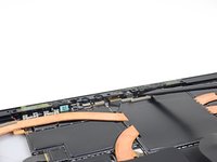
Use a T3 Torx driver to remove the eight 2.2 mm screws securing the motherboard.
-
-
-
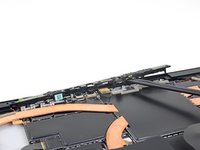
Lift the non-port-side of the motherboard up slightly, just enough so that it clears the components around it and the edge of the case.
-
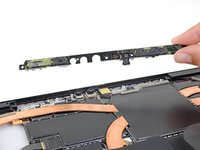
Slide the motherboard away from the ports. Make sure the ports are completely out of their slots in the case before removing the motherboard.
-
Remove the motherboard.
-
-
-
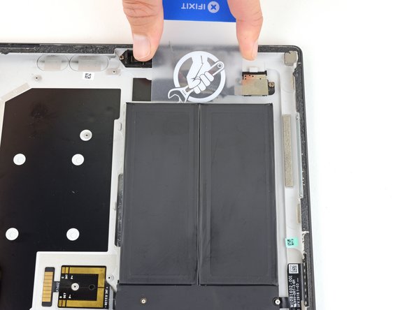
Heat an iOpener and apply it to the battery connector for two minutes to soften the adhesive securing the connector to the case.
-
-
-
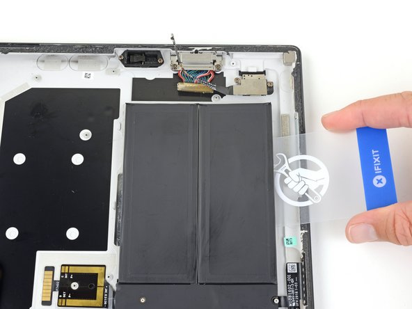
Starting at the edge closest to the battery, slide an opening pick under the battery connector to separate the adhesive underneath.
-
-
-
Prop the top edge of the Surface up a couple inches so the whole Surface slopes towards the bottom edge.
-
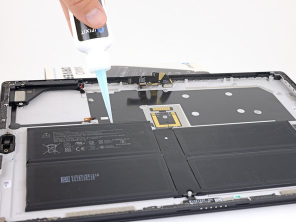
Apply adhesive remover or high-concentration (90% or higher) isopropyl alcohol to the top edge of the battery.
-
Let the adhesive remover sit and soak into the adhesive for 2–3 minutes before continuing.
-
-
この手順で使用する道具:Plastic Cards$2.99
-
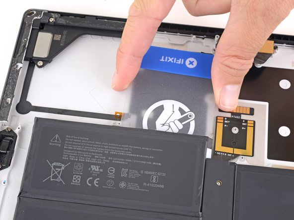
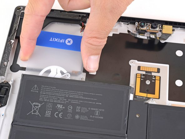
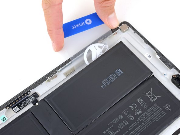
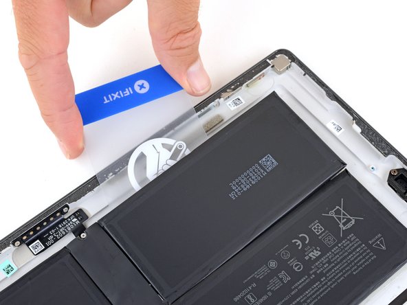
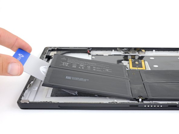
Slide a plastic card under the left side of the top edge of the battery.
-
Slide the card side to side under the upper left battery cell to slice through the adhesive underneath.
-


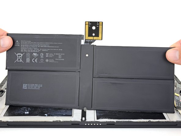


For optimal performance, calibrate your newly installed battery after completing this guide.
Compare your new replacement part to the original part—you may need to transfer remaining components or remove adhesive backings from the new part before installing.
To reassemble your device, follow the above steps in reverse order.
Take your e-waste to an R2 or e-Stewards certified recycler.
Repair didn’t go as planned? Try some basic troubleshooting, or ask our Answers community for troubleshooting help.
29 の人々がこのガイドを完成させました。

10 件のコメント
Das sieht hoch kompliziert aus. Respekt an den Autor und Kritik an Microsoft.
Awesome! Thanks so much. Took me an added 5 hours because I shattered the screen on step 4. Maybe I didn't heat it enough. Maybe because it was already cracked in the corner. Not sure. Luckily, I was replacing the screen anyway and already had a replacement. Good luch y'all. These things were NOT meant to be repaired! I consider myself pretty handy, but I don't think I would have made it without this guide.
Took me 4 hours and the screen is just black, I was super careful, this isn't my first time.
請問版主,我仔細小心得拆下所有部件,並更換了新的電池,也安裝得很順利,沒有拆壞什麼東西,但開啟電源一直停留在黑畫面中間是微軟白色的標誌!請問板主之道是什麼原因嗎?非常感謝,我的電腦是surface Pro 5
Around step 31 for the left speaker, mine had a fan on it. So just disconnect the ribbon cable and there’s a few extra screws but guide worked well. Took 8 hrs for me but the battery paste and screen paste gave me a lot of trouble. The cards in the kit do well for getting the batteries off with hefty remover. Didn’t crack the screen crazy enough.