メインコンテンツにスキップ
MacBook Air 13" Mid 2012 I/O Board Cable Replacement

MacBook Air 13" Mid 2012 I/O Board Cable Replacement

Andrew Optimus Goldheart

Andrew Optimus Goldheart とその他 3 人の作成者

最終更新日: October 12, 2020

見積もりなし
中レベル

Use this guide to replace the I/O board ribbon cable.

必要な工具と部品

パーツ

ツール

もっと見る

  1. MacBook Air 13" Mid 2012 I/O Board Cable Replacement, Lower Case: 手順 1、 1の画像 1
    この手順で使用する道具:
    P5 Pentalobe Screwdriver Retina MacBook Pro and Air
    $5.99
    • Before proceeding, power down your MacBook. Close the display and lay it on a soft surface, top-side down.

    • Use a P5 Pentalobe driver to remove ten screws securing the lower case, of the following lengths:

    • Two 9 mm screws

    • Eight 2.6 mm screws

  2. MacBook Air 13" Mid 2012 I/O Board Cable Replacement: 手順 2、 1の画像 1
    • Wedge your fingers between the display and the lower case and pull upward to pop the lower case off the Air.

    • Remove the lower case and set it aside.

  3. MacBook Air 13" Mid 2012 I/O Board Cable Replacement, Battery Connector: 手順 3、 2の画像 1 MacBook Air 13" Mid 2012 I/O Board Cable Replacement, Battery Connector: 手順 3、 2の画像 2
    • As a precaution against accidental discharge or shock, disconnect the battery connector from the logic board.

    • Grab the clear plastic pull tab attached to the battery connector and pull it toward the front edge of the Air to disconnect the battery from the logic board.

    • Be sure to pull the connector horizontally toward the battery, and not straight up from the Air, or you may damage the socket on the logic board.

  4. MacBook Air 13" Mid 2012 I/O Board Cable Replacement, I/O Board Cable: 手順 4、 1の画像 1
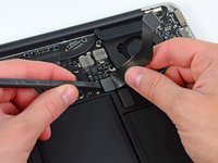
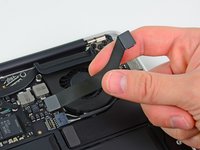
    • Use the flat end of a spudger to pry the I/O board cable connector upward out of its socket on the I/O board.

  5. MacBook Air 13" Mid 2012 I/O Board Cable Replacement: 手順 5、 1の画像 1
    • Carefully peel the I/O board cable from the top of the fan.

  6. MacBook Air 13" Mid 2012 I/O Board Cable Replacement: 手順 6、 2の画像 1 MacBook Air 13" Mid 2012 I/O Board Cable Replacement: 手順 6、 2の画像 2
    • The following connector has an especially deep socket. Use care when disconnecting it.

    • While gently pulling the I/O board cable upward near its connection to the logic board, use the tip of a spudger to pry upward on alternating sides of the connector to help "walk" it out of its socket.

    • Remove the I/O board cable.

終わりに

To reassemble your device, follow these instructions in reverse order.

11 の人々がこのガイドを完成させました。

作成者

3人の作成者と共同で作成されました。

Andrew Optimus Goldheart

メンバー登録日: 10/17/09

508,910 ポイント

407のガイドは作成済み

チーム

iFixit iFixit人のメンバー

Staff

118 メンバー

19,533のガイドは作成済み

0 件のコメント

コメントを追加

統計データ:

過去 24時間: 2

過去 7 日: 5

過去 30 日: 26

今までの合計 6,380