メインコンテンツにスキップ

Interconnect Cables Removal

必要条件のみ
この修理ガイドは、他のガイドの前提条件として使用されます。それ自体は不完全で、単独で使用されることはありません。

必要な工具と部品

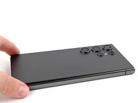
  1. Interconnect Cables Removal, Prepare your phone for disassembly: 手順 1、 2の画像 1 Interconnect Cables Removal, Prepare your phone for disassembly: 手順 1、 2の画像 2
    • Allow your phone's battery to drain below 25%, as a charged lithium-ion battery is a potential safety hazard. If your battery is swollen, take appropriate precautions.

    • Unplug any cables from your phone.

    • Hold the side key and the volume down button, then select "Power off" to turn off your phone.

  2. Interconnect Cables Removal, Heat the right edge: 手順 2、 1の画像 1
    • Heat an iOpener and apply it to the right edge of the back cover for two minutes.

    • You may use a hair dryer, heat gun, or hot plate instead, but be careful not to overheat the phone—the display and internal battery are susceptible to heat damage.

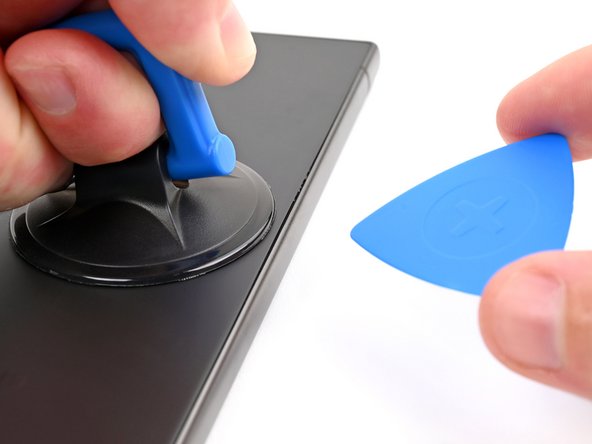
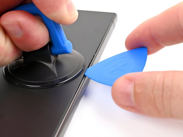
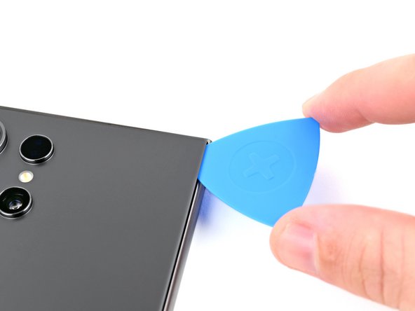
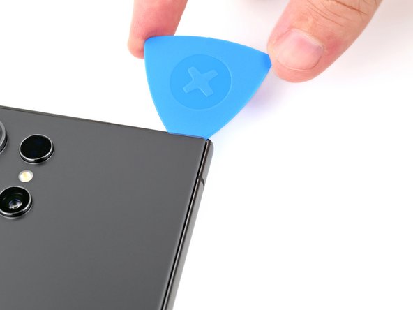
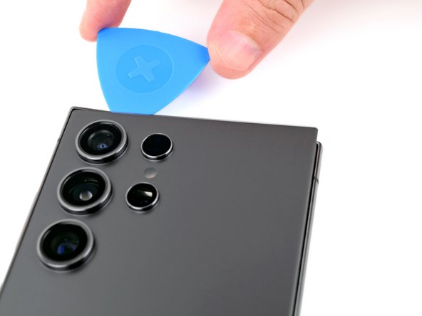
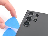
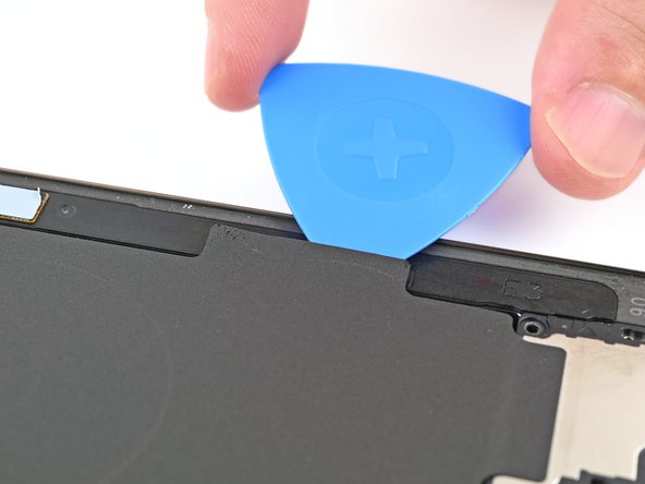
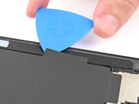
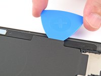
  3. Interconnect Cables Removal, Insert an opening pick: 手順 3、 3の画像 1 Interconnect Cables Removal, Insert an opening pick: 手順 3、 3の画像 2 Interconnect Cables Removal, Insert an opening pick: 手順 3、 3の画像 3
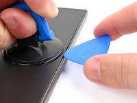
    • Apply a suction handle to the back cover, as close to the center of the right edge as possible.

    • Pull up on the suction handle with strong, steady force to create a gap between the cover and the frame.

    • If you have trouble creating a gap, apply more heat to further soften the adhesive. Follow the iOpener instructions to avoid overheating.

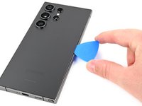
    • Insert an opening pick into the gap.

  4. Interconnect Cables Removal, Separate the right adhesive: 手順 4、 3の画像 1 Interconnect Cables Removal, Separate the right adhesive: 手順 4、 3の画像 2 Interconnect Cables Removal, Separate the right adhesive: 手順 4、 3の画像 3
    • Slide the pick back and forth along the right edge to separate the adhesive.

    • Leave the pick inserted near the bottom right corner to prevent the adhesive from resealing.

  5. Interconnect Cables Removal, Heat the bottom edge: 手順 5、 1の画像 1
    • Apply a heated iOpener to the bottom edge of the back cover for two minutes.

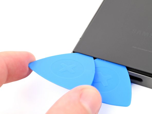
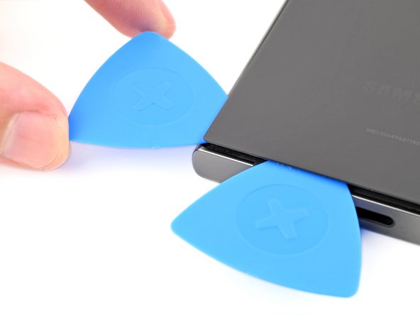
  6. Interconnect Cables Removal, Separate the bottom adhesive: 手順 6、 3の画像 1 Interconnect Cables Removal, Separate the bottom adhesive: 手順 6、 3の画像 2 Interconnect Cables Removal, Separate the bottom adhesive: 手順 6、 3の画像 3
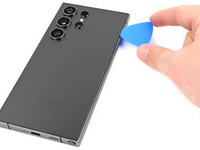
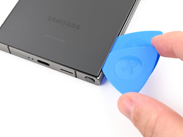
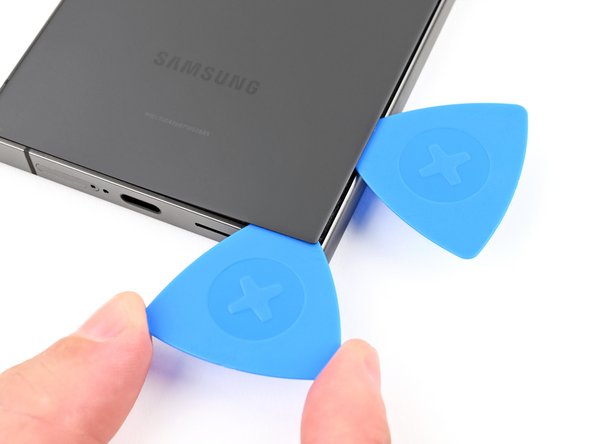
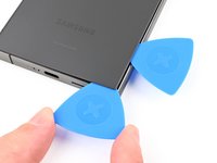
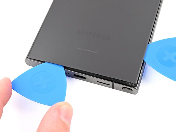
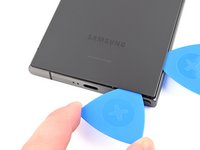
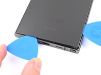
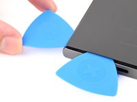
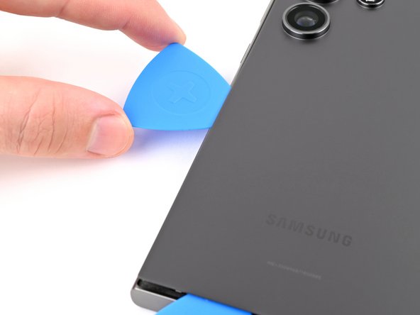
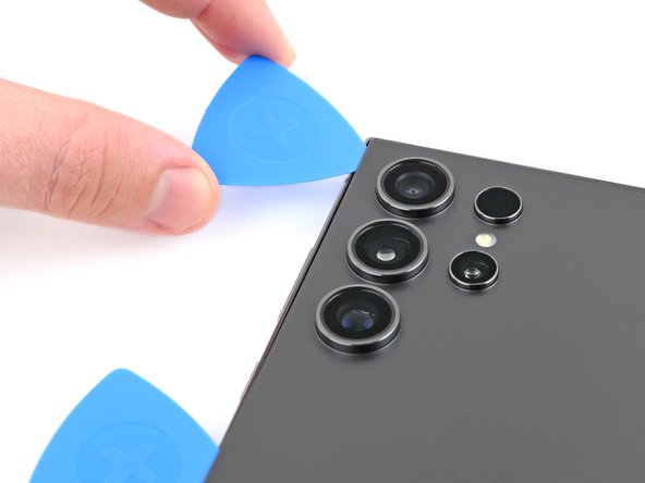
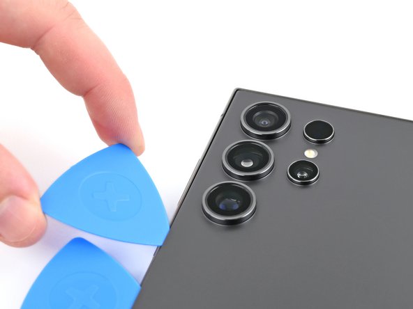
    • Insert a second opening pick next to the first one, near the bottom of the right edge.

    • Rotate the opening pick around the bottom right corner to separate the adhesive.

  7. Interconnect Cables Removal: 手順 7、 2の画像 1 Interconnect Cables Removal: 手順 7、 2の画像 2
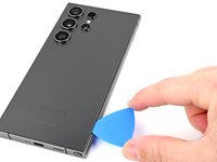
    • Slide the opening pick along the bottom edge to separate the adhesive.

    • Leave the pick inserted near the bottom left corner to prevent the adhesive from resealing.

  8. Interconnect Cables Removal, Heat the left edge: 手順 8、 1の画像 1
    • Apply a heated iOpener to the left edge of the back cover for two minutes.

  9. Interconnect Cables Removal, Separate the left adhesive: 手順 9、 3の画像 1 Interconnect Cables Removal, Separate the left adhesive: 手順 9、 3の画像 2 Interconnect Cables Removal, Separate the left adhesive: 手順 9、 3の画像 3
    • Insert a third opening pick next to the second one, near the left side of the bottom edge.

    • Rotate the opening pick around the bottom left corner to separate the adhesive.

  10. Interconnect Cables Removal: 手順 10、 2の画像 1 Interconnect Cables Removal: 手順 10、 2の画像 2
    • Slide your opening pick along the left edge to separate the adhesive, stopping before you reach the power button.

    • Do not insert the pick more than 4 mm to avoid damaging the antenna cable.

    • Leave the pick inserted near the power button to prevent the adhesive from resealing.

  11. Interconnect Cables Removal, Heat the top edge: 手順 11、 1の画像 1
    • Apply a heated iOpener to the top edge of the back cover for two minutes.

  12. Interconnect Cables Removal, Separate the top adhesive: 手順 12、 3の画像 1 Interconnect Cables Removal, Separate the top adhesive: 手順 12、 3の画像 2 Interconnect Cables Removal, Separate the top adhesive: 手順 12、 3の画像 3
    • Insert an opening pick in the gap at the top of the right edge.

    • Rotate the opening pick around the top right corner to separate the adhesive.

  13. Interconnect Cables Removal: 手順 13、 2の画像 1 Interconnect Cables Removal: 手順 13、 2の画像 2
    • Slide the pick along the top edge to separate the adhesive.

    • Do not insert the pick more than 4 mm to avoid damaging the sensor or camera near the top edge.

  14. Interconnect Cables Removal, Separate the remaining adhesive: 手順 14、 3の画像 1 Interconnect Cables Removal, Separate the remaining adhesive: 手順 14、 3の画像 2 Interconnect Cables Removal, Separate the remaining adhesive: 手順 14、 3の画像 3
    • Slide the pick around the top left corner and down the left edge to separate the remaining adhesive.

    • Do not insert the pick more than 4 mm to avoid damaging the cameras.

  15. Interconnect Cables Removal, Remove the back cover: 手順 15、 2の画像 1 Interconnect Cables Removal, Remove the back cover: 手順 15、 2の画像 2
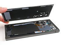
    • Grab and remove the back cover.

    • If your cover is still sticking to the frame, slide an opening pick around the edges to separate any adhesive that may have resealed.

    • During reassembly:

    • This is a good point to power on your phone and test all functions before sealing it up. Be sure to power your phone back down completely before you continue working.

    • Remove any adhesive chunks with a pair of tweezers or your fingers. Apply heat if you're having trouble separating the adhesive.

    • If you're using custom-cut adhesives, follow this guide.

    • If you're using double-sided tape, follow this guide.

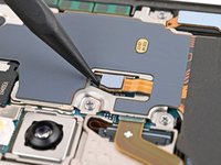
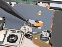
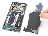
  16. Interconnect Cables Removal, Disconnect the wireless charging coil: 手順 16、 2の画像 1 Interconnect Cables Removal, Disconnect the wireless charging coil: 手順 16、 2の画像 2
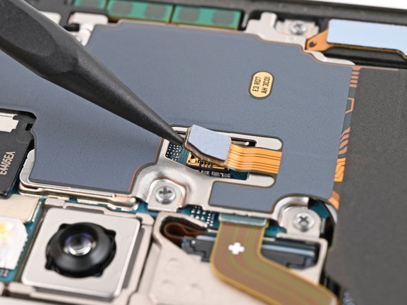
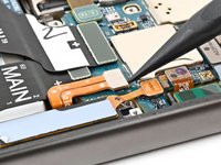
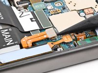
    • Use a spudger to pry up and disconnect the wireless charging coil press connector from the motherboard.

    • There's an arrow printed on the board near each press connector that indicates the recommended prying location. Only pry in this location for each press connector to avoid dislodging surface-mounted components.

    • To reconnect press connectors, align the connector carefully over its socket and press down with your fingertip—first on one side, then the other—until it clicks into place. Don't try to force the connector into place. If you're having trouble, reposition it and try again.

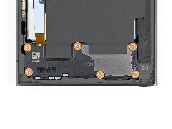
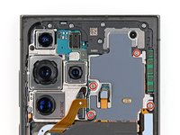
  17. Interconnect Cables Removal, Remove the wireless charging coil and loudspeaker screws: 手順 17、 2の画像 1 Interconnect Cables Removal, Remove the wireless charging coil and loudspeaker screws: 手順 17、 2の画像 2
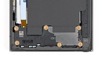
    • Use a Phillips screwdriver to remove the ten 3.5 mm‑long screws securing the wireless charging coil and the loudspeaker:

    • Four screws securing the wireless charging coil

    • Six screws securing the loudspeaker

  18. Interconnect Cables Removal, Separate the coil adhesive: 手順 18、 2の画像 1 Interconnect Cables Removal, Separate the coil adhesive: 手順 18、 2の画像 2
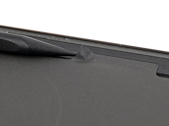
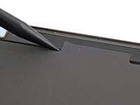
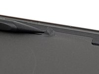
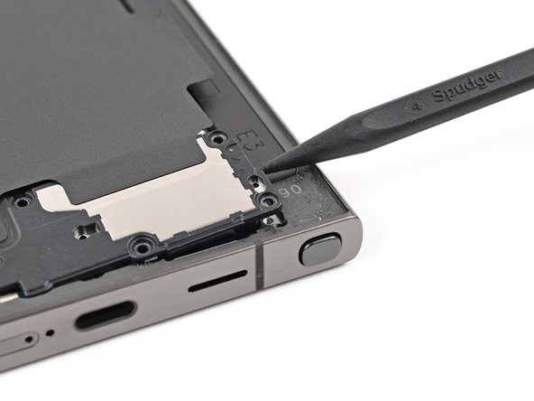
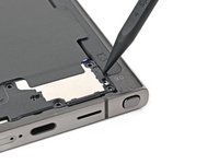
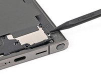
    • Use a spudger to gently pry up a corner of the tab of the wireless charging coil that's adhered to the right edge of the frame.

  19. Interconnect Cables Removal: 手順 19、 2の画像 1 Interconnect Cables Removal: 手順 19、 2の画像 2
    • Use an opening pick to separate the tab from the frame.

  20. Interconnect Cables Removal, Remove the wireless charging coil and loudspeaker: 手順 20、 2の画像 1 Interconnect Cables Removal, Remove the wireless charging coil and loudspeaker: 手順 20、 2の画像 2
    • Insert the point of a spudger into the gap between the right edge of the loudspeaker and the frame.

    • There's an arrow engraved in the loudspeaker to indicate the recommended prying location.

    • Pry up to unclip the loudspeaker from the frame.

  21. Interconnect Cables Removal: 手順 21、 2の画像 1 Interconnect Cables Removal: 手順 21、 2の画像 2
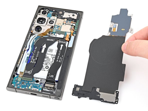
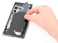
    • Remove the wireless charging coil and loudspeaker from the frame.

    • During reassembly, press around the edges of the loudspeaker to clip it to the frame before reinserting the screws.

  22. Interconnect Cables Removal, Disconnect the battery: 手順 22、 2の画像 1 Interconnect Cables Removal, Disconnect the battery: 手順 22、 2の画像 2
    • Use a spudger to pry up and disconnect the battery press connector.

  23. Interconnect Cables Removal, Disconnect the interconnect cables: 手順 23、 3の画像 1 Interconnect Cables Removal, Disconnect the interconnect cables: 手順 23、 3の画像 2 Interconnect Cables Removal, Disconnect the interconnect cables: 手順 23、 3の画像 3
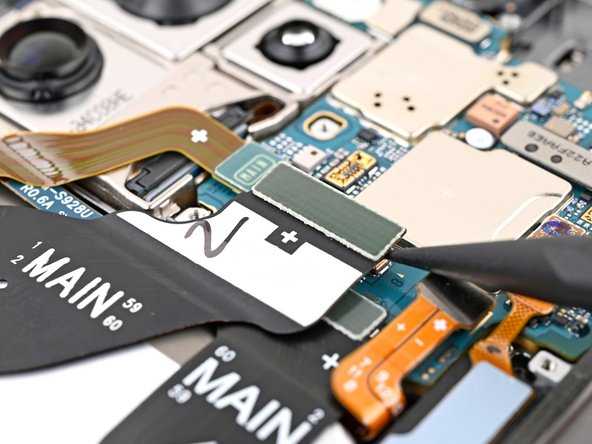
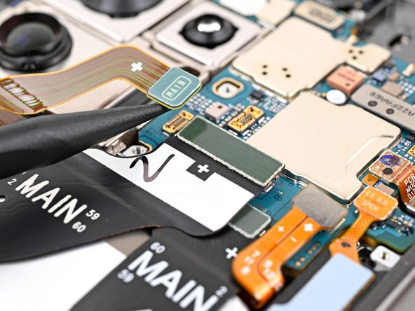
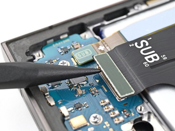
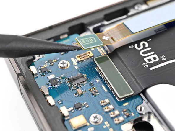
    • Use a spudger to pry up and disconnect both interconnect cable press connectors from the motherboard.

  24. Interconnect Cables Removal: 手順 24、 3の画像 1 Interconnect Cables Removal: 手順 24、 3の画像 2 Interconnect Cables Removal: 手順 24、 3の画像 3
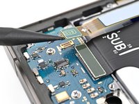
    • Use a spudger to pry up and disconnect both interconnect cable press connectors from the daughterboard.

  25. Interconnect Cables Removal, Remove the interconnect cables: 手順 25、 2の画像 1 Interconnect Cables Removal, Remove the interconnect cables: 手順 25、 2の画像 2
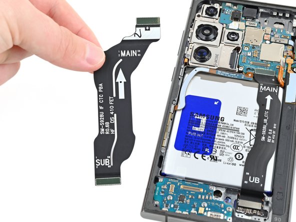
    • Grab and remove the interconnect cables from the phone.

終わりに

To reassemble your device, follow these instructions in reverse order.

Spencer Pennington

メンバー登録日: 09/09/23

17,527 ポイント

114のガイドは作成済み

チーム

iFixit iFixit人のメンバー

Staff

118 メンバー

19,593のガイドは作成済み

0 件のコメント

コメントを追加

統計データ:

過去 24時間: 0

過去 7 日: 0

過去 30 日: 3

今までの合計 15