
G&G Xtreme45 airsoft Disassembly

はじめに
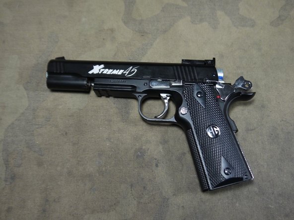
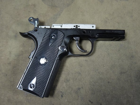
手順 1 に進むThis guide will show how to disassemble the Xtreme45 and allow you to access all major parts groupings. If you wish to just disassemble a particular part or section you may want to skip particular steps.
必要な工具と部品
ツール


もっと見る
-
-
Begin disassembly by removing the small Phillips screws on either side of the slide.
-
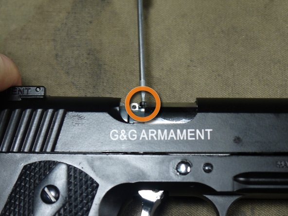
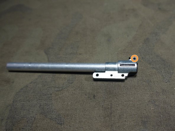
Remove the 1.5mm Hex screw just above the right side Phillips.
-
-
-
-
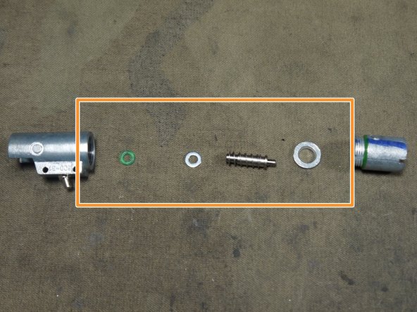
With the pins removed the valve body can be pulled out.
-
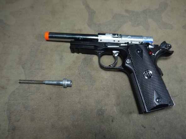
If you wish to further disassemble it you can unscrew the section shown.
-
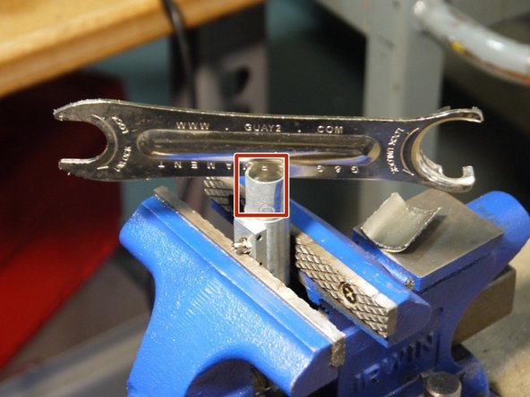
This can be done by taking a long flat piece of metal and use it like a flat head screw driver. The best way to hold the other half is with a vice. Try to avoid using anything that will leave a mark or bend the metal.
-
Once the cap piece has been removed the following piece can be found inside.
-
-
-
To remove the hop-up and inner barrel from the outer barrel first remove the Phillips screw shown.
-
Once that screw is removed you can slide the hop-up and inner barrel out.
-
The hop-up unit is a clam shell design so by removing the screw at the top the hop up splits into two and grants you access to the bucking and barrel.
-


To reassemble your device, follow these instructions in reverse order.
To reassemble your device, follow these instructions in reverse order.
2 の人々がこのガイドを完成させました。

コメント 1 件
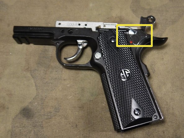
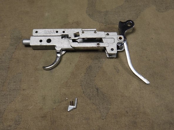
On step 11 picture 1 the trigger is sitting on top of part 1-22, a spring type part, is there any way you can explain the orientation and how it fits back onto the trigger grouping because im having trouble getting the trigger to work after reassembly. Does it have sometging to do with part 1-03? Or is there some other part that im missing.
Heres the guide to see what parts im talking about
Xtreme 45MANUAL - Pnevmat24 https://pnevmat24.ru/image/catalog/files...