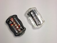
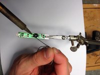
メインコンテンツにスキップ

5 LED 6 Mode Rear Bike Light LED Replacement

必要な工具と部品

  1. 5 LED 6 Mode Rear Bike Light  LED Replacement, 5 LED 6 Mode Rear Bike Light Teardown: 手順 1、 1の画像 1
    • Obtain the necessary tools

  2. 5 LED 6 Mode Rear Bike Light  LED Replacement: 手順 2、 2の画像 1 5 LED 6 Mode Rear Bike Light  LED Replacement: 手順 2、 2の画像 2
    • Insert coin or any flat object into edge of light cover

    • Pry open until cover loosens

  3. 5 LED 6 Mode Rear Bike Light  LED Replacement: 手順 3、 2の画像 1 5 LED 6 Mode Rear Bike Light  LED Replacement: 手順 3、 2の画像 2
    • Remove the single Phillips #00 screw holding the circuit board in place

    • Remove both AAA batteries

  4. 5 LED 6 Mode Rear Bike Light  LED Replacement: 手順 4、 2の画像 1 5 LED 6 Mode Rear Bike Light  LED Replacement: 手順 4、 2の画像 2
    • Remove both Phillips #00 screws holding the clip in place

    • Remove the clip with a flat object

    • The button will fall out when removing the clip. Do not lose it!

  5. 5 LED 6 Mode Rear Bike Light  LED Replacement: 手順 5、 1の画像 1
    • Congratulations! You completed your device teardown!

  6. 5 LED 6 Mode Rear Bike Light  LED Replacement, Remove LEDs: 手順 6、 1の画像 1
    この手順で使用する道具:
    Desoldering Pump
    $3.99
    購入する
    • Warm up the soldering iron

    • Tin the tip of the soldering iron

    • Apply a small amount of solder to the tip

    • Wipe on a damp sponge

    • Touch the tip of the soldering iron to the led solder to liquify it

    • Apply solder wick to absorb solder

    • This guide uses a desoldering pump instead of desoldering wick. The wick would work better.

  7. 5 LED 6 Mode Rear Bike Light  LED Replacement: 手順 7、 1の画像 1
    • Once you remove enough solder, remove the LED

  8. 5 LED 6 Mode Rear Bike Light  LED Replacement, Insert New LED: 手順 8、 2の画像 1 5 LED 6 Mode Rear Bike Light  LED Replacement, Insert New LED: 手順 8、 2の画像 2
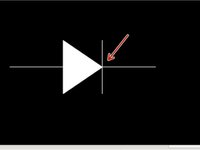
    • Place the new LED through the open holes

    • The LED should cover the schematic symbol on the circuit board and the flat edge of the LED should line up with the tip of the diode symbol shown by the arrow

    • If the LED does not stay, you can tape it in place on the opposite side of the board

    • Warm up the trace on the circuit board and the LED lead with the soldering iron

    • Wipe your soldering iron on the damp sponge every time you pick it up

    • Apply solder to the lead until the hole completely fills with solder

    • Reassemble by following the teardown in reverse order

    • You now have a customized bike light or a working LED!

    • We replaced the middle LED with blue and the two outside LEDs with white. We set the bike light on the last mode. Enjoy!

    • Certain colors of LEDs may be illegal as rear bike lights. Use at your own risk or for a different application!

終わりに

To reassemble your device, follow these instructions in reverse order.

作成者

2人の作成者と共同で作成されました。

Alex Sireci

メンバー登録日: 09/30/13

100 ポイント

2のガイドは作成済み

チーム

Cal Poly, Team 14-8, Forte Fall 2013 Cal Poly, Team 14-8, Forte Fall 2013人のメンバー

CPSU-FORTE-F13S14G8

4 メンバー

8のガイドは作成済み

0 件のコメント

コメントを追加

統計データ:

過去 24時間: 2

過去 7 日: 7

過去 30 日: 16

今までの合計 1,991