
Razer Basilisk V3 Programmable Buttons Replacement

はじめに
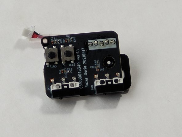
手順 1 に進むThis guide will show you how to replace the four accessory buttons on the mini module of the Razer Basilisk V3. These include two surface-mounted buttons behind the scroll wheel (SW14 and SW15) and two through-hole buttons on the side of the mouse (SW11 and SW12). This repair is necessary if these buttons fail to respond or do not click properly.


-
-
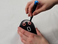
Remove two 4.8 mm screws that were hidden under the skates using a JIS #1 screwdriver.
-
Remove the single 4 mm screw beneath the thumb grip using a JIS #1 screwdriver.
-
-
-
-
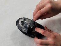
Locate the mini module near the top portion of the mouse.
-
Use a JIS #0 screwdriver to remove the screws securing the module. Two screws measure 4 mm and the remaining two screws measue 10mm.
-
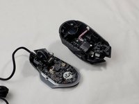
Carefully lift and remove the module from the mouse chassis.
-
-
-
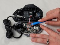
Identify SW2, SW3, and SW4 which are marked on the removed mini module.
-
Use a desoldering pump or solder wick to remove the solder from the contacts of SW14 and SW15.
-
Carefully remove the old buttons using tweezers.
-
Position the new click mechanisms for SW14 and SW15 and secure them by resoldering to the contacts.
-
-
-
Identify SW11 and SW12 which are marked on the removed mini module.
-
Remove the mini module plastic backing piece to allow for the removal of solder.
-
Desolder and remove the old through-hole buttons using similar techniques.
-
Insert the new buttons for SW11 and SW12, ensuring they are properly aligned.
-
Resolder the connections to secure the new buttons in place.
-


Reassemble the mouse by reversing the disassembly process. Ensure all components are securely fastened and the mini module is correctly positioned. Test the functionality of the newly installed buttons to confirm that they are responsive and operating as intended.
Reassemble the mouse by reversing the disassembly process. Ensure all components are securely fastened and the mini module is correctly positioned. Test the functionality of the newly installed buttons to confirm that they are responsive and operating as intended.

チーム

UMass Dartmouth, Team 1-2, Santin Spring 2024 UMass Dartmouth, Team 1-2, Santin Spring 2024人のメンバー
UMASSD-SANTIN-S24S1G2
3 メンバー
11のガイドは作成済み