このバージョンは誤った内容を含んでいる可能性があります。最新の承認済みスナップショットに切り替えてください。
必要な工具と部品
-
-
この手順は未翻訳です。 翻訳を手伝う。
-
This capacitor is only found on older power supplies. Replacement is advised, but not required.
-
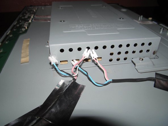
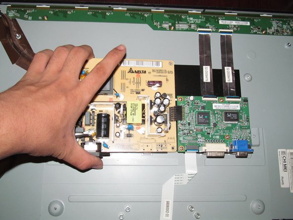
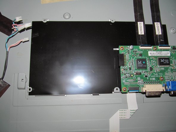
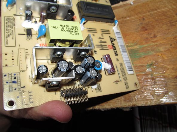
With the power supply shield removed from the monitor, identify the power supply. Take note of the values, including the inverter cap (if present).
-
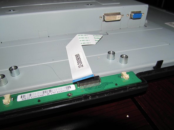
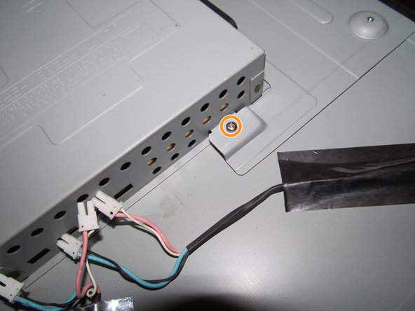
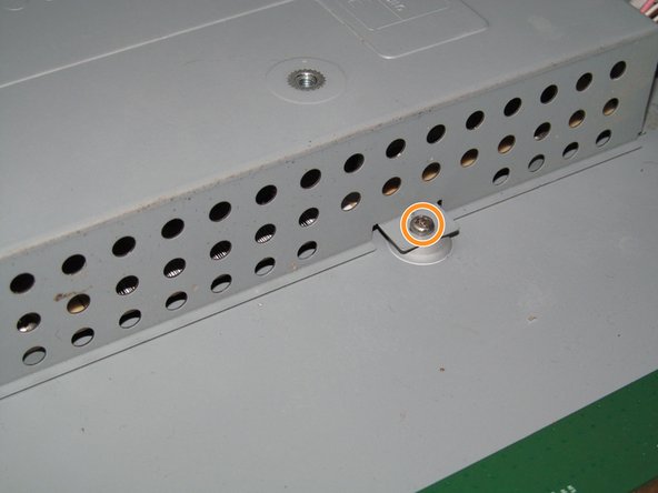
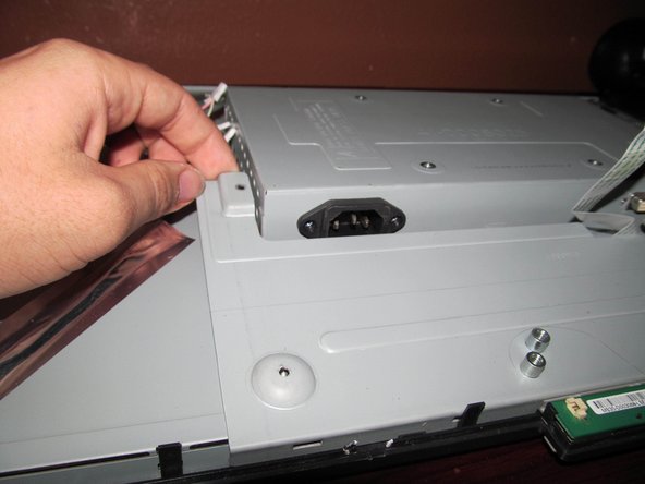
Remove the 4 screws from the power supply. Once this is done, lift up the power supply at a slight angle to clear the chassis. Do not lift too much or the connector may be damaged!
-
-
この手順は未翻訳です。 翻訳を手伝う。
-
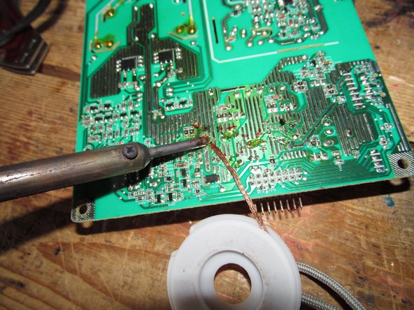
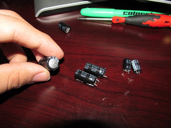
Move to a workspace with ventilation or use a fume extractor. Once in an appropriate workspace, desolder the old capacitors. Heat up each leg and remove it.
-
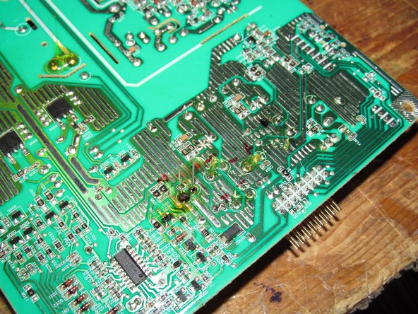
After removing the capacitors, clean up the old solder with a desoldering braid. Lift it with the iron when removing it.
-


12 の人々がこのガイドを完成させました。

チーム

28 件のコメント
I did not replace the large capacitor on the Acer monitor yet. All other caps have been replaced. I may have to replace the FSPO55- ZP102A as it has a hot spot beside it. I don't know if the part number is right? Do know where I can buy it. Tom B
These older CCFL panels usually burn on the PCB by the inverter coil and main transformer (the Delta branded part, in this case). The LED monitors limit the failure points to the transformer.
It sounds like your PCB got burned from the heat by the transformer or the inverter coil. This is very common and the boards are designed to take it. However, if you are concerned you should buy a new power supply board altogether if that makes you more comfortable.
Nick -
In step 12, replacing the capacitors with ones with a different capacitance rating instead of using a capacitor rated for higher voltage makes no sense to me electrically. The capacitance rating is the important part, if you use a capacator rated for say 35 volts when the original is rated for 10 makes no difference whatsoever. the rating just means MAX voltage.