はじめに
Follow this guide to replace the vibration motor in your Samsung Galaxy A15.
To reassemble your device, you will need replacement adhesive for the vibration motor and back cover.
必要な工具と部品
-
-
Unplug all cables and completely power off your phone.
-
Press and hold the power and volume down buttons at the same time to bring up the shutdown menu.
-
-
-
Heat an iOpener and apply it to the right edge of the back cover for two minutes.
-
-
-
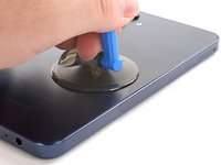
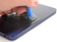
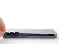
Apply a suction handle to the back cover, as close to the center of the right edge as possible.
-
Pull up on the suction handle with strong, steady force to create a gap between the cover and the frame.
-
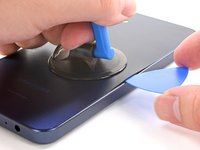
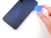
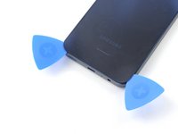
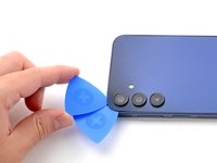
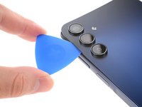
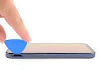
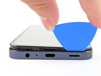
Insert an opening pick into the gap.
-
-
-
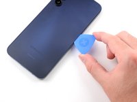
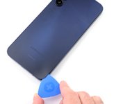
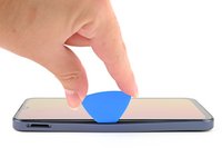
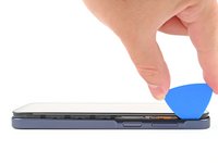
Slide your opening pick along the right edge between the back cover and the frame to slice through the adhesive.
-
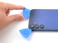
Leave your opening pick in the bottom right corner to keep the adhesive from resealing.
-
-
-
-
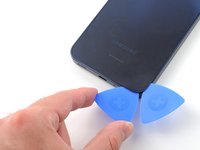
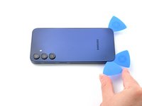
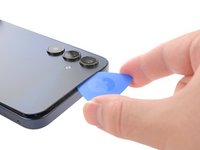
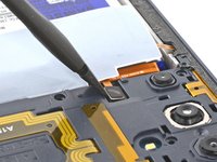
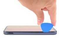
Insert your opening pick along the top edge of the phone and twist it gently to unfasten the camera clips.
-
Slide your opening pick around the edge of the camera modules to unfasten the remaining camera clips.
-
-
-
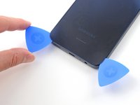
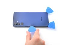
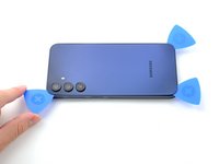
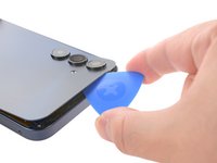
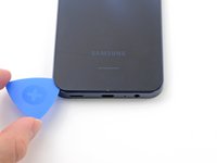
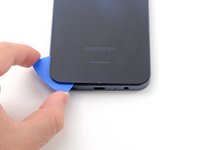
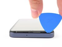
Once the adhesive around the edges is loose, insert your opening pick deeper into the bottom edge from the bottom left corner.
-
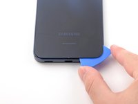
Slide your pick deeper into the phone across the bottom edge, slicing the remaining adhesive.
-
-
-
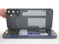
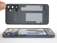
Lift and remove the back cover.
-
Remove any adhesive chunks with a pair of tweezers or your fingers. Apply heat and isopropyl alcohol (90% or greater) if you're having trouble removing the adhesive.
-
If you're using custom-cut adhesives, follow this guide.
-
If you're using double-sided tape, follow this guide.
-
-
この手順で使用する道具:iFixit Precision 4 mm Screwdriver Bit$2.99
-
Insert a SIM card eject tool, bit, or a straightened paperclip into the hole on the SIM tray, located towards the top of the phone on the left edge.
-
Press in firmly to eject the tray and remove it.
-
-
-
Remove the fifteen 4 mm-long screws connecting the frame to the chassis.
-
-
-
Use the flat end of a spudger to pry up and disconnect the fingerprint button press connector from the motherboard.
-
-
-
Insert your opening pick above the SIM card tray cutout to form a gap between the frame and the phone.
-
Slide your opening pick down the left edge of the device to unfasten the frame clips.
-
-
-
Use the flat end of a spudger to lift up and disconnect the battery press connector from the motherboard.
-
-
-
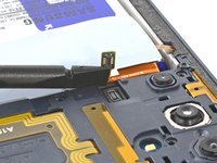
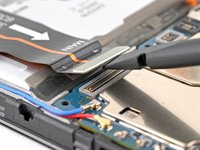
Insert the flat end of a spudger under the overhang of the top "OCTA" cable connector.
-
Pry up the top connector away from the bottom one until they're disconnected.
-
-
-
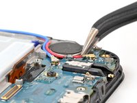
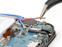
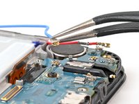
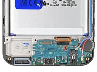
Insert one arm of your angled tweezers under the metal neck of the red antenna coaxial connector on the daughterboard and lift straight up to disconnect it.
-
Repeat for the other connector.
-
-
この手順で使用する道具:Tesa 61395 Tape$2.99
-
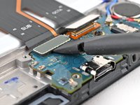
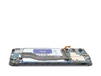
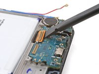
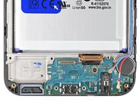
Insert your spudger underneath the flex ribbon connector and pry it off of the board.
-
-
-
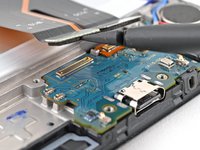
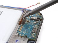
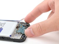
Use your Phillips screwdriver to remove the 3 mm‑long screw securing the daughterboard to the phone.
-
-
-
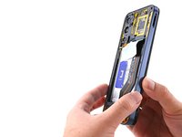
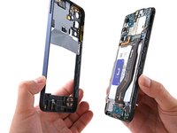
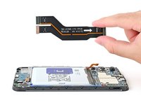
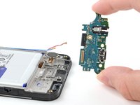
Grab the daughterboard by its edges and pull it up and out of the phone.
-
-
この手順で使用する道具:Tesa 61395 Tape$2.99
-
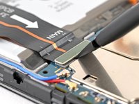
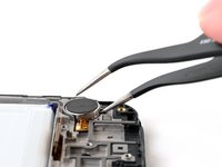
Insert one arm of your angled tweezers into the notch under the vibration motor.
-
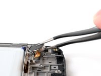
Grab the motor with your tweezers and lift it to separate its adhesive.
-
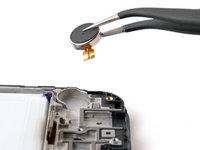
Remove the vibration motor.
-


Compare your new replacement part to the original part—be sure to transfer remaining components and remove adhesive backings from the new part before installing.
To reassemble your device, follow these instructions in reverse order.
Repair didn’t go as planned? Try some basic troubleshooting, or ask our Answers community for help.
ある他の人がこのガイドを完成しました。

