はじめに
この修理ガイドはGoogle Pixel 8aの基板を外す方法です。
必要な工具と部品
-
-
デバイス左端にあるSIMカードトレイの穴に、SIM取り出しツール、ビット、またはまっすぐに伸ばしたペーパークリップを、しっかりと押し込んで、トレイを取り出します。
-
SIMカードトレイを取り出します。
-
-
-
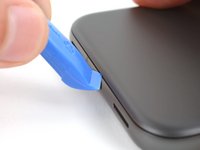
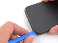
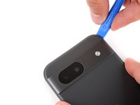
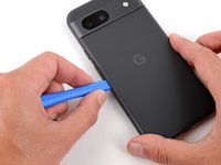
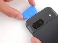
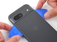
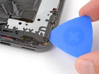
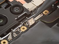
特に異なる指示がない場合、工具を3mm(オープニングツールの平らになっている部分の幅)以上深く縁に差し込まないでください。
-
カメラ部の突起の縁には工具を差し込まないでください。
-
-
-
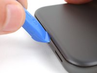
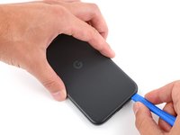
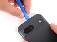
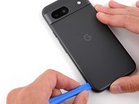
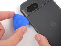
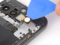
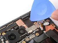
オープニングピックを背面カバーの左上の角に差し込み、先端が先端がカメラ部の突起の上端付近に届くまで差し込んでください。
-
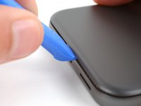
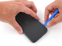
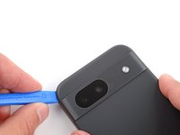
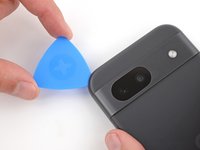
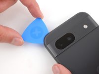
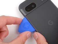
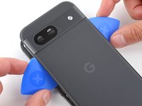
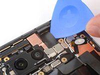
オープニングピックを右に滑らせて、カメラの右端まで動かしたら止めて下さい。
-
-
-
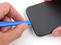
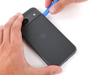
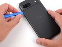
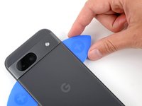
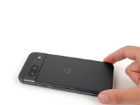
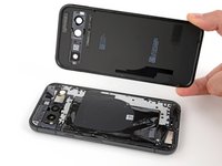
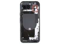
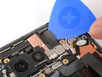
これで背面カバーが外せるようになりました。
-
スマートフォンを密封する前にテストするなら、今がちょうど良いタイミングです。電源を入れて正しく機能するか確認して下さい。組み立て直しを続ける前に電源を切るのを忘れないでください。
-
こちらのガイドを参照して、新しい接着剤と背面カバーを取り付けて下さい。
-
-
-
この手順で使用する道具:FixMat$36.95
-
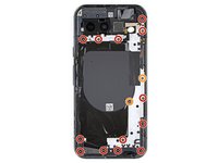
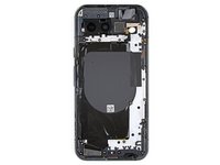
トルクスプラス3IPドライバーを使って、ロジックボードカバーを固定している合計15本のネジを外して下さい。
-
長さ4.3mmのネジ 13本
-
長さ1.9mmのネジ 2本
-
-
-
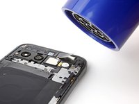
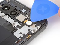
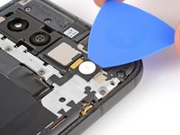
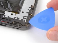
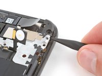
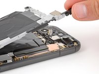
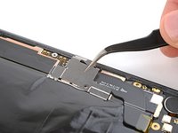
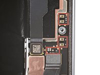
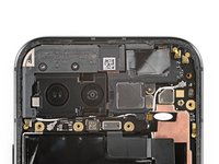
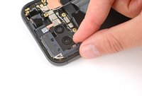
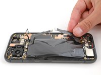
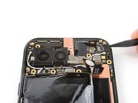
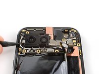
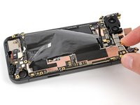
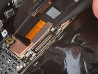
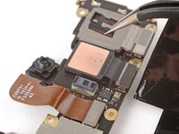
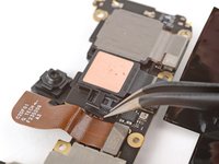
スパッジャーの先端を基板右上コーナー付近のくぼみの下に差し込み、こじ上げてボードのクリップを外します。
-
同じ作業を繰り返し、カメラの左側にあるくぼみを使ってボードの反対側のクリップを外します。
-
-
-
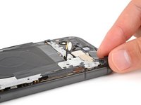
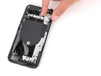
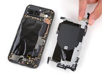
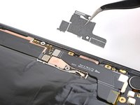
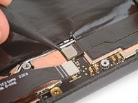
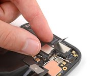
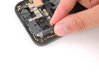
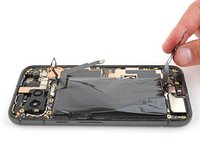
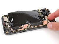
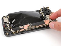
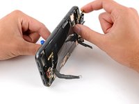
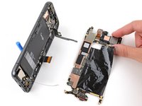
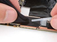
基板の上端をフレームから持ち上げます。
-
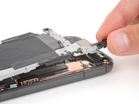
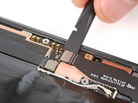
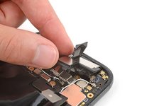
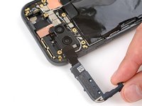
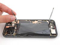
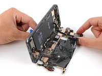
基板の切り欠きが振動モーターとフレームの突起上を越えるように、基板の上端をフレームの右側に引っ張ります。
-
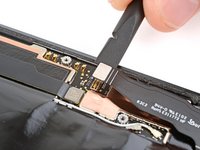
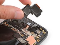
引っ張る際、充電ポートをフレームのくぼみから誘導して出します。
-
-
-
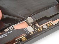
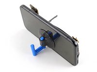
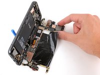
吸盤ハンドルを画面の左側に、ハンドルが下を向くように取り付けます。
-
スマートフォンの左側を立てて、まっすぐ立つようにします。
-
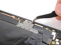
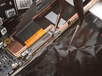
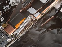
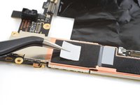
基板を下に傾けて平らに置き、繊細なグラファイトシートをケーブルの周辺に配置します。
-
-
-
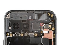
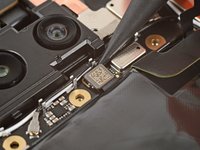
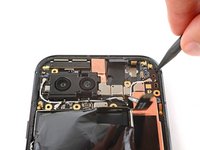
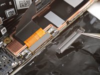
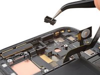
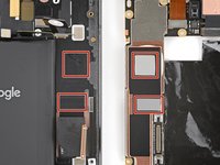
放熱パッドの状態を確認します。これらは基板の底面、またはフレームの右側の対応する位置にあります。
-
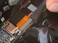
基板を再利用する場合で、どちらかの放熱パッドが損傷している場合は、古いパッドを取り除き、高濃度のイソプロピルアルコール(90%以上)で表面を清掃してから、新しいパッドを貼り付けてください。
-
新しい基板に放熱パッドが取り付けられていない場合は、この時点で新しいパッドを取り付けてください。
-


デバイスを再組み立てする際は、これらの修理ガイドを逆の順番に従って作業を進めてください。
以下の翻訳者の皆さんにお礼を申し上げます:
100%

Midori Doiさんは世界中で修理する私たちを助けてくれています! あなたも貢献してみませんか?
翻訳を始める ›

