メインコンテンツにスキップ

このバージョンは誤った内容を含んでいる可能性があります。最新の承認済みスナップショットに切り替えてください。

必要な工具と部品

  1. , ボトムカバー: 手順 1、 2の画像 1 , ボトムカバー: 手順 1、 2の画像 2
    • 先に進む前に、コンピュータの電源を切り、充電器を外してください。

    • ラップトップカバーを裏返して、底面を上にします。

    • 7mm T5トルクスネジを10本外します。

  2. : 手順 2、 2の画像 1 : 手順 2、 2の画像 2
    • 開口ツールで、底カバーをこじ開けます。

    • カバー正面端から初めて、両側もスライドしながらこじ開けます。

  3. : 手順 3、 1の画像 1
    • ボトムカバーを持ち上げて、後ろのヒンジから外します。

  4. , バッテリー: 手順 4、 3の画像 1 , バッテリー: 手順 4、 3の画像 2 , バッテリー: 手順 4、 3の画像 3
    • 指またはピンセットを使って、バッテリーワイヤーを引っ張っりながら小刻みに動かし、バッテリーコネクタを外します。

    • ケーブルの接続をゆっくりと外します。コネクタに繋がった8本のワイヤはとても小さくデリケートです。ご注意ください。

  5. : 手順 5、 2の画像 1 : 手順 5、 2の画像 2
    • 4mm #1プラスネジを4本外します。

  6. : 手順 6、 1の画像 1
    • バッテリーを引き上げて、筐体から外します。

    • バッテリーを慎重に取り扱ってください。端子に接触すると感電することがあります。またバッテリーに穴をあけてしまうと引火の原因となります。

  7. , 左側ファン: 手順 7、 1の画像 1
    • ラップトップを裏返して、左側ファンがSSDとワイヤレスカード付近の右側に配置してください。

    • 黒と白のアンテナワイヤを、ファンの右側にある溝から外します。

  8. : 手順 8、 2の画像 1 : 手順 8、 2の画像 2
    • ファンケーブルの接続を外します。ワイヤを揺らしながら接続を外しながら、ラップトップ右側に向けて、ワイヤを引っ張ります。

    • コネクタの白いタブを使って、ケーブルを押し出して外すこともできます。

  9. : 手順 9、 2の画像 1 : 手順 9、 2の画像 2
    • 4mm #1プラスネジを2本外します。

  10. : 手順 10、 1の画像 1
    • ファンをラップトップ正面側に向けて引っ張り、本体から外します。

  11. , 右側ファン: 手順 11、 1の画像 1
    • ラップトップを裏返して、左側ファンが大型のメタルRAMカバー付近の左側に配置してください。

    • ファンケーブルの接続を外します。接続を緩めるため、ラップトップの後ろ側に向けてワイヤを引っ張ります。

    • コネクタの白いタブを使って、ケーブルを押し出して外すこともできます。

  12. : 手順 12、 2の画像 1 : 手順 12、 2の画像 2
    • 4mm #1プラスネジを2本外します。

  13. : 手順 13、 1の画像 1
    • ファンをラップトップ正面側に向けて引っ張り、本体から外します。

  14. この手順は未翻訳です。 翻訳を手伝う。

    : 手順 14、 3の画像 1 : 手順 14、 3の画像 2 : 手順 14、 3の画像 3
    • Remove the fingerprint reader ribbon cable located at the bottom left of the motherboard.

    • Pull up on the black tab on the connector.

    • The ribbon cable should easily pull out of the connector.

  15. この手順は未翻訳です。 翻訳を手伝う。

    : 手順 15、 2の画像 1 : 手順 15、 2の画像 2
    • Remove the three other ribbon cables at the lower edge of the motherboard.

    • For each, lift up the black tab on the connector.

    • The ribbon cables should easily pull out of the connectors.

  16. この手順は未翻訳です。 翻訳を手伝う。

    : 手順 16、 3の画像 1 : 手順 16、 3の画像 2 : 手順 16、 3の画像 3
    • Disconnect the speaker cable by pulling the wire towards the front of the laptop.

    • You can also use the white tabs on the connector to push the cable free.

  17. この手順は未翻訳です。 翻訳を手伝う。

    : 手順 17、 1の画像 1
    • Remove the sticky tape from the top of the wireless card.

  18. この手順は未翻訳です。 翻訳を手伝う。

    : 手順 18、 3の画像 1 : 手順 18、 3の画像 2 : 手順 18、 3の画像 3
    • Pull the black and white antenna wires off of the wireless card.

    • For reassembly, the white wire connects to the right terminal marked "1." The black wire connects to the left terminal marked "2."

  19. この手順は未翻訳です。 翻訳を手伝う。

    : 手順 19、 2の画像 1 : 手順 19、 2の画像 2
    • Pull up on the thick gray display cable near the back of the laptop to disconnect the display.

  20. この手順は未翻訳です。 翻訳を手伝う。

    : 手順 20、 3の画像 1 : 手順 20、 3の画像 2 : 手順 20、 3の画像 3
    • The charger port is connected to the computer by a cable at the top left of the motherboard.

    • Disconnect the cable by pulling the bundle of wires firmly toward the back of the laptop.

    • The cable requires some force to remove. Make sure you do not damage the connector or cable.

  21. この手順は未翻訳です。 翻訳を手伝う。

    : 手順 21、 2の画像 1 : 手順 21、 2の画像 2
    • Remove four 4mm Phillips #1 screws.

  22. この手順は未翻訳です。 翻訳を手伝う。

    : 手順 22、 1の画像 1
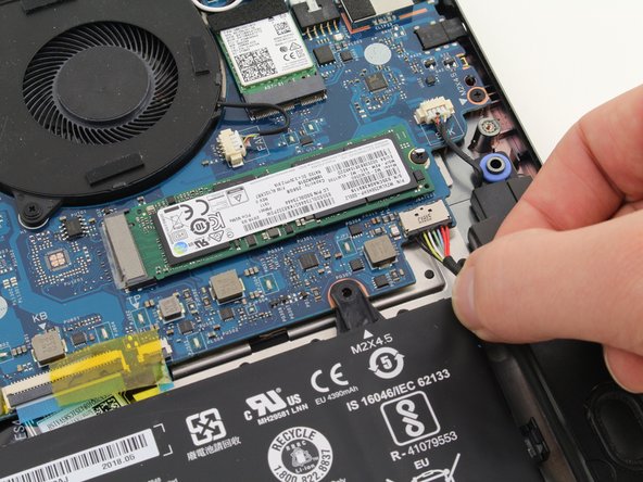
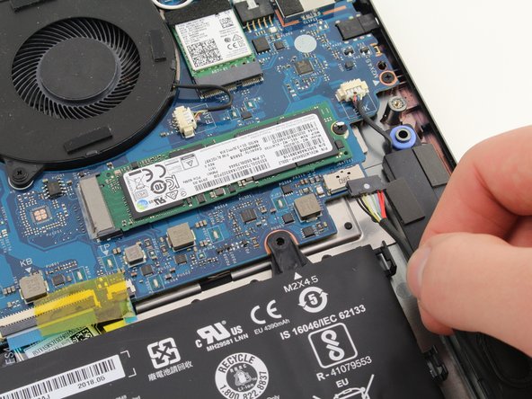
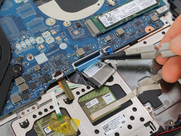
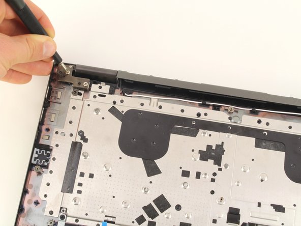
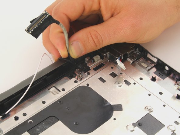
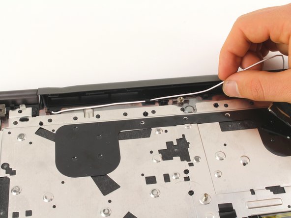
    • Pull the motherboard up out of the laptop chassis.

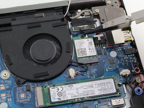
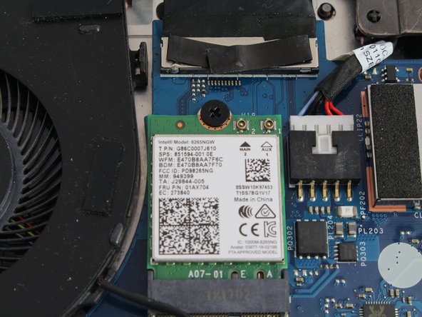
    • If you are replacing the motherboard, make sure to remove the SSD, wireless card, heat sink, and extra RAM. Transfer these components to the new motherboard.

  23. この手順は未翻訳です。 翻訳を手伝う。

    : 手順 23、 2の画像 1 : 手順 23、 2の画像 2
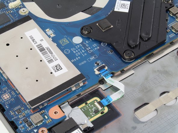
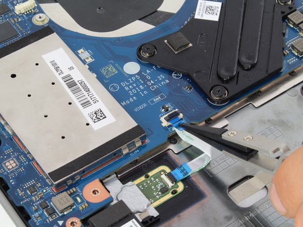
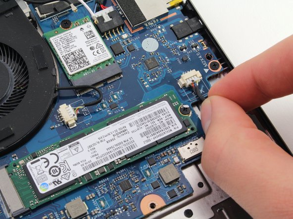
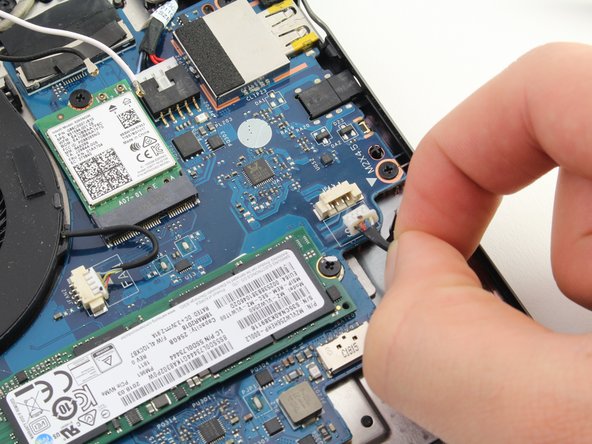
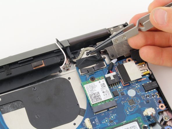
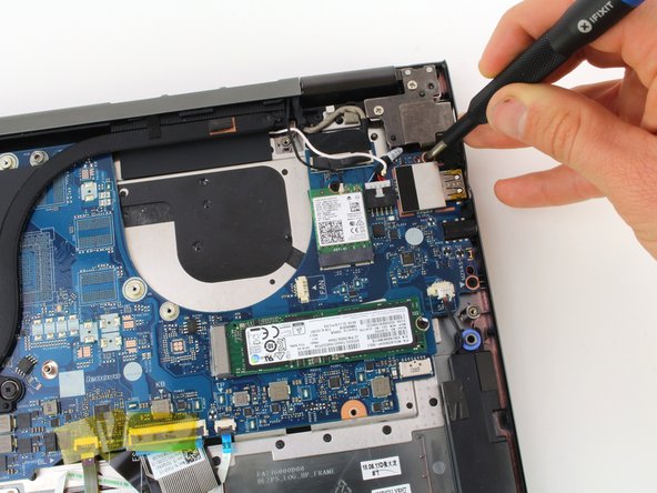
    • Remove four 4mm (silver colored) Phillips #1 screws.

    • For reassembly, pay close attention to where you reattach these screws. The holes closest to the corner need to be left free. They will be used when you reattach the back cover.

  24. この手順は未翻訳です。 翻訳を手伝う。

    : 手順 24、 3の画像 1 : 手順 24、 3の画像 2 : 手順 24、 3の画像 3
    • Pull the thick gray display cable out from under the hook that holds it in place.

    • Remove the white antenna wire from underneath the hooks near the back of the laptop.

  25. この手順は未翻訳です。 翻訳を手伝う。

    : 手順 25、 2の画像 1 : 手順 25、 2の画像 2
    • Tilt the keyboard up to make a 90 degree angle with the screen. This makes it easier to move the display and antenna cables.

    • On the back of the keyboard, slide the white antenna cable past the edge of the hinge.

    • Pull the keyboard upward and towards the front of the screen to make room for the cable.

  26. この手順は未翻訳です。 翻訳を手伝う。

    : 手順 26、 1の画像 1
    • Pull the thick display cable and the black antenna cable past the hinge.

    • Tilt the left side of the keyboard upward. This helps create some room around the hinge.

  27. この手順は未翻訳です。 翻訳を手伝う。

    : 手順 27、 1の画像 1
    • Pull the keyboard up away from the screen. After the display and antenna wires have been moved, the keyboard should easily come apart from the screen.

ゴール

3 の人々がこのガイドを完成させました。

作成者

3人の作成者と共同で作成されました。

Ellis Ruckman

メンバー登録日: 01/23/20

2,545 ポイント

6のガイドは作成済み

チーム

Cal Poly, Team S1-G6, White Winter 2020 Cal Poly, Team S1-G6, White Winter 2020人のメンバー

CPSU-WHITE-W20S1G6

3 メンバー

27のガイドは作成済み

コメント 1 件

Isn't this missing "How to disassemble the LCD Panel" ? I'll try to take some decent pictures while I'm putting mine back together. Does anyone know where I can buy some of that special adhesive tape that behind this screen?

Nathan - 返信

コメントを追加

統計データ:

過去 24時間: 1

過去 7 日: 16

過去 30 日: 96

今までの合計 9,386