このバージョンは誤った内容を含んでいる可能性があります。最新の承認済みスナップショットに切り替えてください。
必要な工具と部品
-
-
コンデンサ放電ツールを作るには、まず必要な材料を集めます。以下のようなものがあります:
-
ワイヤの長さは2本。電源、電動モーター始動回路、カメラのフラッシュ回路に使用される大型電解コンデンサ用で、最低必要なワイヤーは12AWG、600ボルトの定格電圧です。
-
コンデンサを放電する際に発生する熱エネルギー量を放散させるために定格された抵抗器です。電源や電動モーターの起動回路、カメラのフラッシュ回路などに使用される大型の電解コンデンサーでは20kΩ5w、小型のコンデンサーでは2kΩ5wが最低条件となります。
-
収縮チューブ
-
-
-
この手順は未翻訳です。 翻訳を手伝う。
-
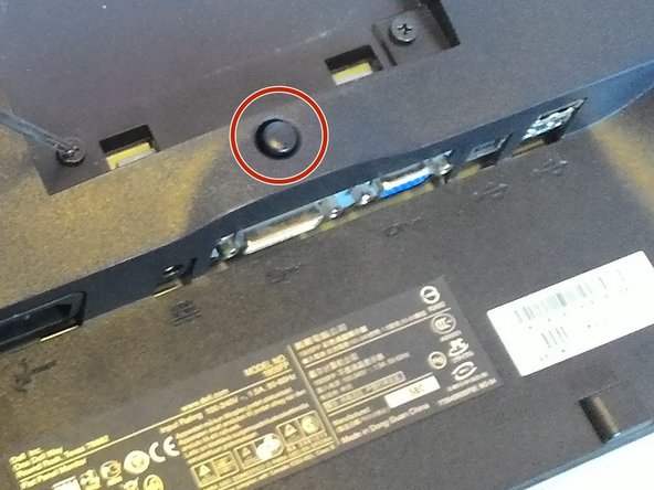
Flip the monitor around and locate the two slots on the edges. These slots are below the screen where the faceplate is attached.
-
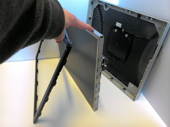
Use a flat tool (such as a flathead screwdriver) to pop the front frame off. It is attached via plastic snaplocks and will come off with some prying.
-
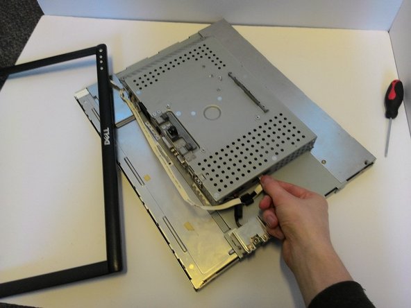
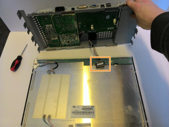
Once the faceplate is removed, the monitor can be removed from the housing, leaving the monitor and the faceplate attached with a ribbon wire. The wire can now be pulled from the slot, fully removing the faceplate from the monitor.
-
-
この手順は未翻訳です。 翻訳を手伝う。
-
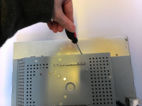
Remove the plates protecting the wires. There are a total of 5 screws holding two plates onto the top and bottom.
-
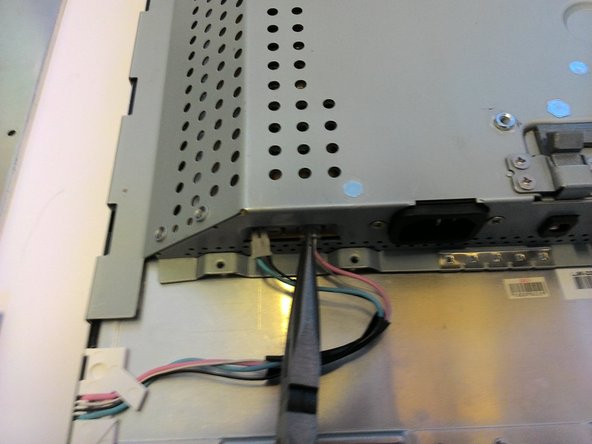
With the plates removed, we can now unplug the 2 green and 2 pink wires connecting the electronics to the screen. This is best done with needle nose pliers, since the attaching head must be depressed and pulled at the same time.
-
-
この手順は未翻訳です。 翻訳を手伝う。
-
After all the capacitors are safely discharged, flip the housing over and remove the three indicated screws from the back.
-
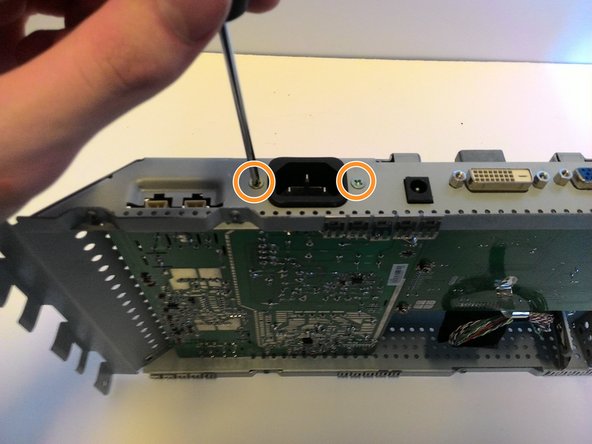
Flip it onto its side and remove the two screws attaching the powerboard to the power port.
-
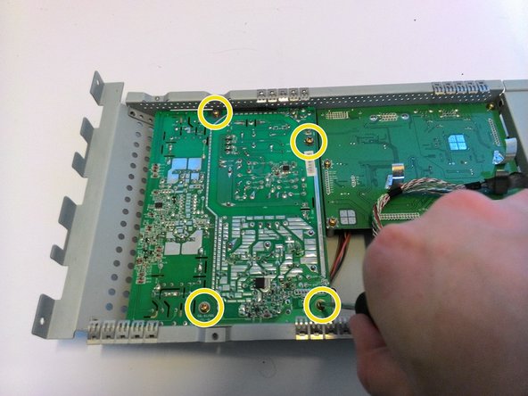
Remove the four screws from the powerboard itself. This frees the powerboard from the housing.
-
-
この手順は未翻訳です。 翻訳を手伝う。
-
Now you can remove and manipulate the circuit board.
-
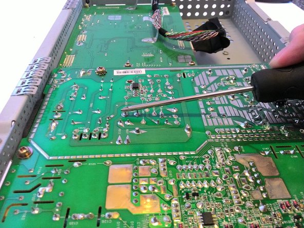
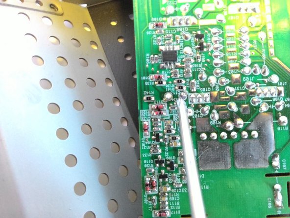
Locate any capacitors that are blown. The tops will be rounded rather than flat or could have dried orange fluid spilling from the tops. These need to be replaced. Identify their capacitance and voltage and remember these.
-
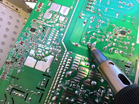
Using a soldering iron and desoldering tape, remove the solder attaching any blown capacitors.
-


4 の人々がこのガイドを完成させました。

チーム

Michigan Tech, Team 1-4, Lauer Spring 2016 Michigan Tech, Team 1-4, Lauer Spring 2016人のメンバー
MTU-LAUER-S16S1G4
1 メンバー
3のガイドは作成済み
コメント 1 件
I seem to have a different board layout inside my DELL 1905FP. Maybe they differ internationally because of the built-in transformator.
Found and replaced the faulty capacitors on the transformator board. It is aliiiive :)
Thanks for the guide. Opening the case from the front frame first was the trick, I was looking for.