Apple AirPort Express Base Station Power Supply Kit
はじめに
A common issue with the Apple AirPort Express is that its power supply tends to burn out. This guide will show you how to open your AirPort, build your own power supply, and install the new power supply.
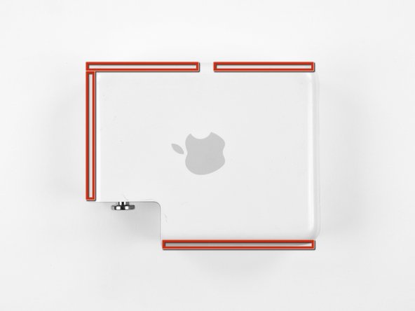
Mark or note the edges that need to be cut to open the AirPort Express case.
Use a dremel tool with a thin cutting bit to slowly cut around the marked edges. Cut evenly along the middle of the edges, and make several shallow passes to ensure that you don't accidentally cut into any of the components inside.
If you see sparks while cutting, it means you are cutting through the EMI shields. Reduce your cutting depth immediately to prevent further damage.
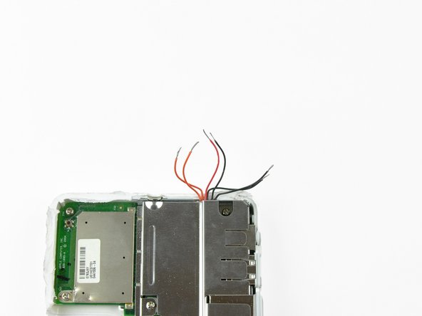
Be especially cautious when cutting next to the LED light, as the power wires are right next to the case wall. The wires are highlighted in orange in the third picture. Severing these wires may make the repair extremely difficult.
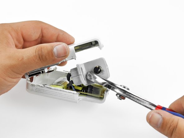
Use a metal spudger or prying device to begin levering the case halves apart.
Do not push the prying device too far into the case, as this could damage the EMI shields or other components.
The case will be most stubborn near the grey power inlet, as this piece is glued to the case halves. Focus on separating the other parts of the case first.
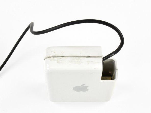
Remove the grey power inlet from the case half it is still attached to. Use a pair of pliers to rock the power inlet back and forth until it breaks free from the glue.
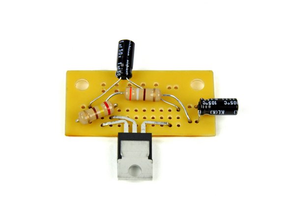
The printed circuit board (PCB) supplied in your kit can be soldered using any rails that you desire. However, we have determined that using the following rails provides a nice, low-profile, fit.
The power inlet and outlet wires are recommended to be soldered in the following locations, though again they can be soldered to any through-hole you desire along the proper trace.
Place the pins of the voltage regulator through the holes indicated in step 7. Adjust the pins if necessary.
There should be just a small portion of the pin sticking up through the top side of the PCB. If the pins do not stick through the board, adjust the pin bends so that they do.
Solder the pins to the board on the printed side of the PCB.
Unsure of how to properly through-hole solder? Check out our technique guide. You can even use a thin piece of wire and practice with a hole on an unused trace.
Try to solder quickly and efficiently. Prolonged application of heat to any of the component pins can transfer enough heat to damage it.
Insert the leads of the 390 Ω resistor through the holes indicated in step 7. This resistor will have an orange, grey, brown and gold band on it. The direction of the resistor does not matter.
Be sure to route the leads so that they do not cover any of the indicated holes in steps 7 and 8.
Solder the resistor to the PCB and clip off the excess leads.
Insert the leads of the 240 Ω resistor through the holes indicated in step 7. This resistor will have a red, yellow, brown, and gold band on it. The direction of the resistor does not matter.
Be sure to route the leads so that they do not cover any needed holes from steps 7 and 8. Also, do not allow the leads to contact the leads of other components.
Solder the resistor to the PCB and clip the excess leads off.
Insert the leads of the 1 µF capacitor through the holes indicated in step 7. The capacitor will have markings on it indicating its capacitance. The direction of the capacitor does not matter.
Be sure to route the leads so that they do not cover any needed holes from step 7 or 8. Also, do not allow the leads to contact the leads of other components.
Solder the capacitor to the PCB and clip off the excess leads.
Insert the leads of the .1 µF capacitor through the holes indicated in step 7. The capacitor will have markings on it indicating its capacitance. The direction of the capacitor does not matter.
Be sure to route the leads so that they do not cover any needed holes from steps 7 and 8. Also, do not allow the leads to contact the leads of other components.
Solder the capacitor to the PCB and clip the excess leads off.
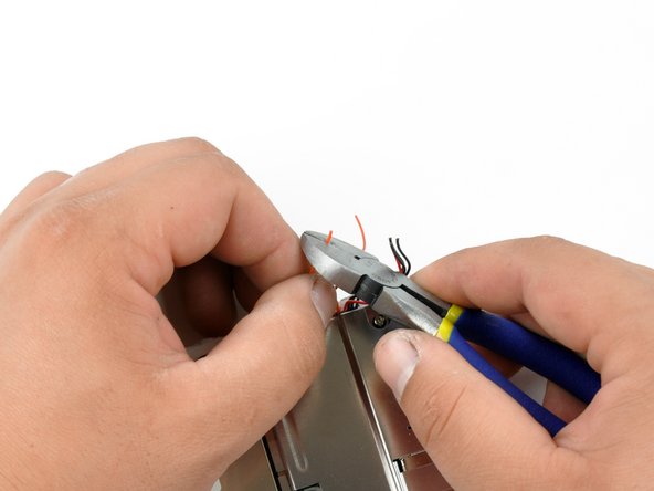
Cut the lead off of the power supply included in the kit.
You can cut the power supply leads as short as you desire to reduce clutter.
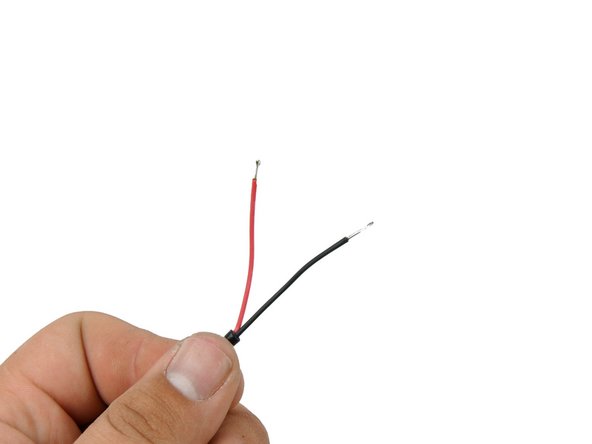
Strip the outer sheath off the wires. You can use either wire strippers with the correct size hole, or you can use a pair of wire cutters to carefully cut just the outer sheath.
Pre-tin the exposed wires to add rigidity to them and keep them from fraying when pushing through the PCB through-holes.
Pre-tinning is when you cover or fill wires with solder to improve a solder connection. Be sure that your pre-tin does not have any globs on it, or it will not fit through the PCB through-holes. If necessary, trim the wire so that it will fit through the holes.
Align the pre-tinned section of the cut wire with one of the lower case power wires. Melt the two pre-tinned sections together length-wise. Repeat for the remaining two wire sets.
Slip a piece of shrink tubing over each of the exposed solder joints.
Use the soldering iron to apply a little heat evenly around each of the shrink tubing pieces until they are secured to the wire.
Do not hold the soldering iron to the shrink tubing pieces for more than a few seconds at a time. You may accidentally de-solder the wires or even break the shrink tubing.
We recommend using the side of the soldering iron when applying heat to the shrink tubing. The sides are cooler than the tips, and using the sides will also prevent solder from getting on the shrink tubing or vice-versa.
Insert and solder the wires from the AirPort board into the appropriate holes of the PCB.
The red-wired lead goes to the 5 V out hole from step 8.
The orange-wired lead goes to the 3.3 V out hole from step 8.
The black-wired lead goes to the ground out hole from step 8.
After soldering these wires is the perfect time to give your new power supply a quick test. Plug in the power supply and see if the LED on the lower case half turns on. If it does, your power supply is working. If it doesn't, quickly unplug the power supply and recheck all your connections.
You can test output using a multimeter and checking the voltage at the red (5 V) and orange (3.3 V) wire solder joints and using the black wire solder joint as ground. Variations of no more than .3 V is acceptable.
Secure the PCB to the upper case half using the original 5.38 mm #1 Phillips screw and the included washer.
Do not over-tighten the screw or you will break the screw hole.
Be sure to orient the PCB so that the voltage regulator points towards where the grey power inlet used to be.
Peel the white back off the thermal pad, being careful not to accidentally peel the thermal pad off of the heat sink.
Set the heat sink onto the voltage regulator so that their lower left corners, as oriented in the third picture, are aligned. Press the heat sink firmly onto the voltage regulator to ensure that it will stick.
Put the case halves together. Be careful not to pinch the 3 power leads, and be sure to route the power supply cable out of the opening in such a way that it won't put tension on any of the PCB components.
There are likely large burrs (shredded plastic bits) on the edges of your case from cutting it open. For ease of joining the case halves, it is recommended that you smooth the edges by de-burring them. A dremel tool with a sanding bit, a sanding block, or a knife will work for this process.
Pour a small amount of the plastic beads that were included with the kit into a heat- and stick-resistant container.
Use a heat gun to heat the plastic beads until they turn transparent.
Most hair driers are also capable of melting the beads. If neither a hair drier of sufficient power nor a heat gun are available to you, you can also try boiling them and straining them out of the boiling water.
When using a heat gun or hair dryer, be sure to turn the heat to high but leave the fan on low, or you will blow the beads out of the container!
Give the plastic beads a few seconds to cool, then remove them and mash them together until they form one piece.
The plastic beads should be fairly warm still, but their container will likely be extremely hot. Use care when removing and handling the beads.
Stretch the glob of plastic into a thin strip that will fill one of the gaps between the case halves.
Press the plastic into the crevices and smooth it out with your finger.
If the plastic becomes too hard to work with, you can re-apply heat to loosen the plastic.
Be cautious if you reheat the plastic while it's in the case. Allow cooling periods between reheating so you don't accidentally de-solder any components.
When you are satisfied with the smoothness and fill of the crevice, allow the case and plastic to cool for approx 10-15 minutes. The plastic filler will become a milky white color when it is fully solidified.
Repeat steps 29 through 35 for all of the crevices created from cutting the case.
It is highly recommended that you leave the old power inlet hole unsealed to allow some cooling for your new power supply.
Allow the case to cool for at least an hour when you have finished sealing it. This will prevent you from starting the AirPort Express while components are too hot.
Try to operate your AirPort Express in an open and/or well ventilated location. Initial failure can result from over-heating, and over-heating can still cause your new power supply, or any of the other components, to fail.
First of all: thanks for creating this all-in-one repair kit.
Now my question: it looks like it is based a US power adapter (in 110V). Therefore, I was wondering if you have done the same kit for Europe (220V) since it does not appear on your EU store.
Is it possible to add battery here – to make wireless airport for music listening by Apple's Airplay (Wi-fi)?
Bluetooth is awful for music with no quality at all until we get someday 5.0
I noticed that Apple's airport express is getting hot during operation, maybe this problem can be managed with getting rid of converting power supply (battery direct needed voltage).
Firstly thanks for the excellent repair kit. Everything is great with the repair until I’ve hit the same issue as Johan, in that the ribbon cable between the two halves are all black. When you look at the PCB it helpfully says 3.3V and GND. In a leap of faith I’ve assumed (always dangerous!) that the loom is identical to Phillip’s teardown in that Apple wouldn’t go to the lengths of massive redesigns between versions and have grouped the wires as per two orange, one red, three black (using my all black connector) but there’s no joy. I haven’t released any magical blue smoke yet but am loathed to try random configurations of wires. Can anyone help please? I can post photos if necessary


