The iPod Touch 4th Generation front panel is attached to the rear case by adhesive. The use of a heat gun to soften the adhesive is highly recommended.
With the heat gun set on "low", begin heating the lower portion of the Touch near the home button.
It is suggested to heat the desired portion in a circular motion pattern to evenly dissipate the amount of heat throughout the device.
When there is enough room to grab the bottom edge of the front panel, lift it away from the body of the Touch to peel up the adhesive along its left and right edges.
If the adhesive is too difficult to separate, use a heat gun to soften it before proceeding.
Due to the construction of the 4th generation Touch, the digitizer cable cannot be disconnected until the logic board is removed. Use extreme caution when handling the front panel assembly, as it is attached to the rest of the Touch by the very delicate digitizer cable.
Also, the display data cable is very short and is connected to the logic board near the top of the front panel assembly. If it does not become disconnected while freeing the top edge of the front panel assembly, be sure to disconnect it with an iPod opening tool before rotating the front panel assembly out of the Touch.
Carefully pull the top of the front panel assembly away from the adhesive holding it to the Touch, minding the short digitizer cable connecting the two components.
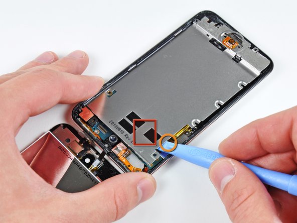
Insert the edge of an opening tool under the steel mid plate near the bottom left corner of the Touch.
Slowly pry upward to separate the plate from the adhesive securing it to the plastic inner case.
If the plate is still attached to the logic board, re-warm the area to loosen the adhesive, then slowly separate the plate from the logic board using the opening tool.
There is a thin, fragile ribbon cable underneath the plate. As you pry the plate up, be very careful not to rip the cable.
This cable may stick to the plate and will tear very easily if you're not careful. Work slowly and be careful not to strain the cable.
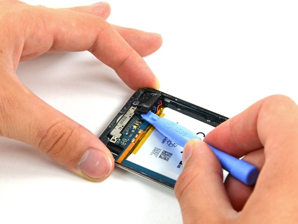
Use an iPod opening tool to slightly lift the edge of the logic board next to the battery enough to grab it with your other hand.
Do not excessively bend the logic board, as it is very thin and fragile.
Be very careful not to lift too much as the volume control ribbon cable is still connected and will tear very easily.
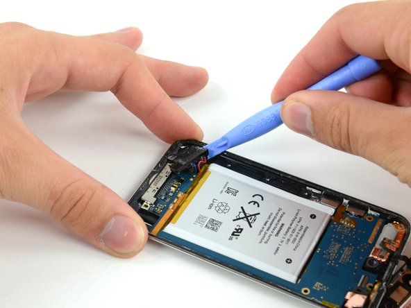
While gently lifting the logic board with one hand, use an iPod opening tool to lift the logic board near the copper tape at the logic board's top edge.
The logic board will be lifted adequately when the last display assembly connector has cleared the top edge of the rear case.
In the next few steps, you will loosen the adhesive from underneath the battery, the logic board, and the frame under the battery. Do this slowly, carefully, and evenly. Take care not to puncture the battery or bend the logic board.
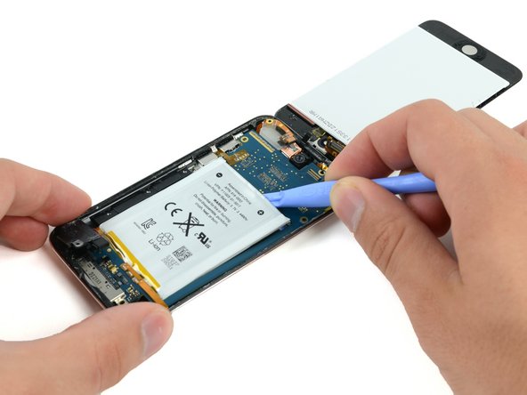
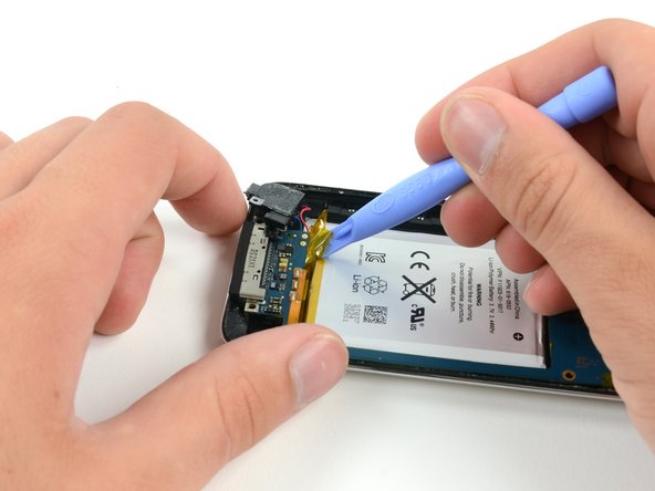
Use a plastic opening tool to pry up the adhesive around the three exposed edges of the battery.
Do not try to pry the battery out, just start loosening the adhesive.
After the edges of the battery are loosened, begin prying up the edge of the logic board. Start at the top and work your way down the side of the board.
To prevent bending/breaking the logic board, do not try to remove the logic board, yet. The dock connector is still embedded in the frame. Again, you are only trying to loosen more of the adhesive.
With a plastic opening tool, carefully push the dock connector out of its outer case recess. Work each corner evenly until the connector comes free.
Since the dock connector is attached to the logic board, pushing it out of the case may cause the logic board to begin to flex. Take extra care not to permanently warp the board.
Once all of the adhesive is freed from under the logic board/battery assembly, lift the assembly up from the side and carefully rotate it over to access the underside of the battery.
The logic board is still attached to the rear case. Do not try to completely separate the assembly, or you will rip this ribbon cable.
Grip the copper shield located on the bottom of the battery with one hand while firmly holding the battery with the other.
Carefully peel the copper shield up off the battery.
Do not rapidly peel the copper shield. Doing so may cause irreversible damage to the battery.
When installing a new battery, the copper shield must be as flat as possible. Otherwise the ruffled shield will add to the thickness of the battery and LCD combined.
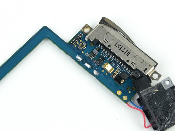
In the next few steps, you will desolder the three battery solder joints on the logic board.
Prior to desoldering the 3 leads, there may be some silicon/glue covering them. Remove as much as possible with a plastic or metal spudger (if metal, be extremely careful not to bridge the connections) before applying soldering tip to points.
The battery on the fourth generation Touch is attached via solder pads with small holes that go through the battery ribbon cable and attach to flat pads on the face of the logic board. In this step, you will heat each solder pad individually while using a metal spudger to pry it up from the logic board.
DO NOT bridge the connection between the solder pads both on the board and on the ribbon cable with your spudger. Shorts have the potential to ruin the logic board.
Beware of overheating the board and the cable. Only hold the tip of the iron against the pad long enough to let the solder melt. Excess heat buildup has the potential to ruin the logic board or melt the ribbon cable.
Start working from the outside of the battery ribbon cable. Heat the outermost solder pad while gently prying up from under the ribbon cable to free it from the board. Repeat this process for each of the two remaining pads, working from the outside in.
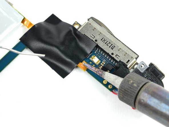
Place the new battery in place and align the far contact with the outer solder pad. Use a small strip of electrical tape to hold the cable against the solder pads.
Installing the battery upside down (with the cable facing up) will destroy the logic board.
Place the strip of tape over the end of the battery ribbon cable to cover two of the solder pads and hold the contacts down against the logic board.
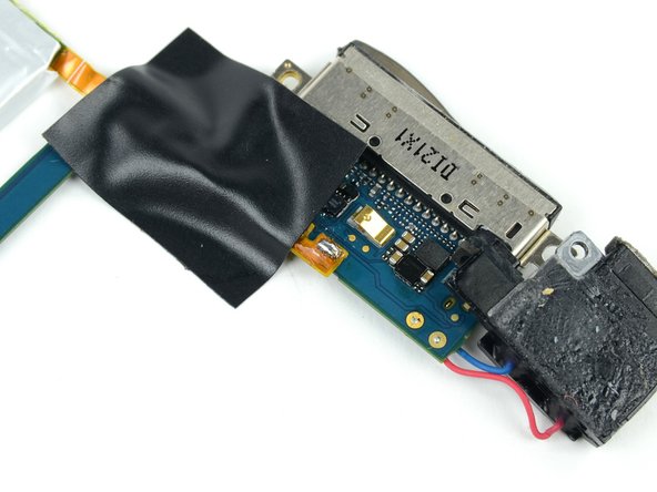
Heat the rightmost contact until the solder below melts, then apply a small amount of solder to the contact, allowing it to flow through the two holes in the cable and down to the logic board.
Do not apply too much solder. The amount required for a proper bond is miniscule.
As soon as the solder has flowed into the joint, remove both the solder and the iron.
Move the piece of tape so that it no longer covers the remaining two leads. If you are satisfied with the position of the cable relative to the pads on the board, proceed. If not, de-solder the first connection and try again.
Solder the two remaining pads to the logic board, being mindful of overheating the cable or board.
I had a similar problem when pressing on the center button. Turns out it was too much solder on the battery connector. I had to disassemble again and used some solder wick to lower the solder blobs. I suspect that the back plate must not be completely flat for you.
To clarify, does the battery show as charging when plugged in? If so, will it go from no/low charge back up to half charge? If this is the case, I would contact whoever sold you the battery and ask for a replacement.