メインコンテンツにスキップ

Switch Pro Controller Motherboard Replacement

必要な工具と部品

  1. Switch Pro Controller Motherboard Replacement, Remove the screws: 手順 1、 1の画像 1
    • Flip the controller over so the model stickers face the ceiling.

    • Use a JIS #00 screwdriver to remove the two black 8.4 mm screws that secure the handles, located at the ends of the handles.

  2. Switch Pro Controller Motherboard Replacement, Remove the handle covers: 手順 2、 3の画像 1 Switch Pro Controller Motherboard Replacement, Remove the handle covers: 手順 2、 3の画像 2 Switch Pro Controller Motherboard Replacement, Remove the handle covers: 手順 2、 3の画像 3
    • Carefully remove the handle covers by pulling them away from the main body.

  3. Switch Pro Controller Motherboard Replacement, Remove the screws: 手順 3、 1の画像 1
    • Use a JIS #00 screwdriver to remove the four silver 6.8 mm screws that secure the clear back plastic cover.

  4. Switch Pro Controller Motherboard Replacement, Unclip the plastic cover: 手順 4、 3の画像 1 Switch Pro Controller Motherboard Replacement, Unclip the plastic cover: 手順 4、 3の画像 2 Switch Pro Controller Motherboard Replacement, Unclip the plastic cover: 手順 4、 3の画像 3
    • Carefully pry away the clear plastic cover using your fingernail.

  5. Switch Pro Controller Motherboard Replacement, Remove the clear plastic cover: 手順 5、 1の画像 1
    • Remove the clear plastic cover.

  6. Switch Pro Controller Motherboard Replacement, Remove the battery: 手順 6、 3の画像 1 Switch Pro Controller Motherboard Replacement, Remove the battery: 手順 6、 3の画像 2 Switch Pro Controller Motherboard Replacement, Remove the battery: 手順 6、 3の画像 3
    • Remove the lithium-ion battery by using a fingernail or plastic opening tool to pry it up on the left side.

    • Only a small amount of force is needed.

  7. Switch Pro Controller Motherboard Replacement, Remove the screws: 手順 7、 3の画像 1 Switch Pro Controller Motherboard Replacement, Remove the screws: 手順 7、 3の画像 2 Switch Pro Controller Motherboard Replacement, Remove the screws: 手順 7、 3の画像 3
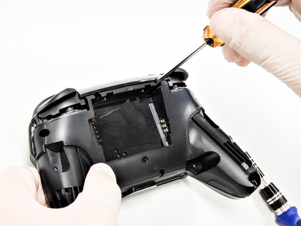
    • Use a Phillips #1 screwdriver to remove the five 5 mm screws from the back of the controller.

    • The two case screws above the handgrips and the single case screw below the battery bay have a shallow seat. These three screws can be easily removed.

    • The two case screws adjacent to the ZR and ZL shoulder buttons have a deep seat. Use an extension or a Phillips screwdriver with a longer shaft to reach these screws.

  8. Switch Pro Controller Motherboard Replacement: 手順 8、 3の画像 1 Switch Pro Controller Motherboard Replacement: 手順 8、 3の画像 2 Switch Pro Controller Motherboard Replacement: 手順 8、 3の画像 3
    • There's an adhesive pad located in the center of each handle. It will require a bit of force to pry away the front cover, but be mindful of the attached ribbon cable.

    • Delicately take off the plastic cover from the controller.

    • Don't completely remove the front cover just yet, as it's still attached to the motherboard via a white ribbon cable.

  9. Switch Pro Controller Motherboard Replacement, Open the flap: 手順 9、 2の画像 1 Switch Pro Controller Motherboard Replacement, Open the flap: 手順 9、 2の画像 2
    • Use the tip of an opening pick to open the black flap of the ZIF connector by pushing it upwards.

  10. Switch Pro Controller Motherboard Replacement, Disconnect the interconnect cable: 手順 10、 2の画像 1 Switch Pro Controller Motherboard Replacement, Disconnect the interconnect cable: 手順 10、 2の画像 2
    • Use your fingers or a pair of blunt nose tweezers to disconnect the interconnect cable from its connector.

  11. Switch Pro Controller Motherboard Replacement, Remove the front case: 手順 11、 1の画像 1
    • Remove the front case.

  12. Switch Pro Controller Motherboard Replacement, Remove the joystick caps: 手順 12、 3の画像 1 Switch Pro Controller Motherboard Replacement, Remove the joystick caps: 手順 12、 3の画像 2 Switch Pro Controller Motherboard Replacement, Remove the joystick caps: 手順 12、 3の画像 3
    • With light force pull the two joystick caps off of the controller.

  13. Switch Pro Controller Motherboard Replacement, Loosen the adhesive: 手順 13、 2の画像 1 Switch Pro Controller Motherboard Replacement, Loosen the adhesive: 手順 13、 2の画像 2
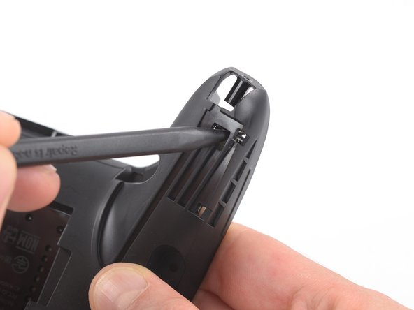
    • Insert the tip of a spudger from the back into the hole on the right controller handle.

    • Push the spudger through the hole to loosen the adhesive which is holding rumble modules in their places.

  14. Switch Pro Controller Motherboard Replacement, Loosen the adhesive: 手順 14、 2の画像 1 Switch Pro Controller Motherboard Replacement, Loosen the adhesive: 手順 14、 2の画像 2
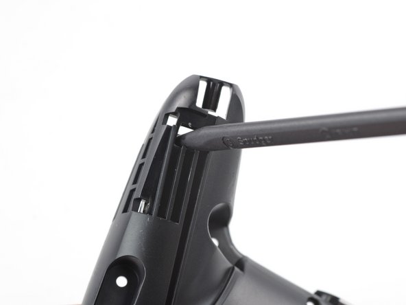
    • Insert the tip of a spudger from the back into the hole on the left controller handle.

    • Push the spudger through the hole to loosen the adhesive which is holding rumble modules in their places.

  15. Switch Pro Controller Motherboard Replacement, Lift the modules: 手順 15、 2の画像 1 Switch Pro Controller Motherboard Replacement, Lift the modules: 手順 15、 2の画像 2
    • Use a pair tweezers to lift the modules out of their places.

  16. Switch Pro Controller Motherboard Replacement, Unscrew the motherboard: 手順 16、 1の画像 1
    • Use a Phillips screwdriver to remove the four 5 mm-long screws securing the motherboard.

  17. Switch Pro Controller Motherboard Replacement, Remove the LED light: 手順 17、 3の画像 1 Switch Pro Controller Motherboard Replacement, Remove the LED light: 手順 17、 3の画像 2 Switch Pro Controller Motherboard Replacement, Remove the LED light: 手順 17、 3の画像 3
    • Use your thumb or a pair of tweezers to to take off the white LED light housing.

  18. Switch Pro Controller Motherboard Replacement, Lift the motherboard: 手順 18、 3の画像 1 Switch Pro Controller Motherboard Replacement, Lift the motherboard: 手順 18、 3の画像 2 Switch Pro Controller Motherboard Replacement, Lift the motherboard: 手順 18、 3の画像 3
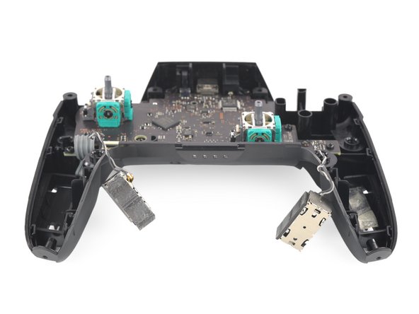
    • Lift the motherboard carefully as to not damage the wires and flip it to reveal the backside.

  19. Switch Pro Controller Motherboard Replacement, Desolder the rumble modules: 手順 19、 3の画像 1 Switch Pro Controller Motherboard Replacement, Desolder the rumble modules: 手順 19、 3の画像 2 Switch Pro Controller Motherboard Replacement, Desolder the rumble modules: 手順 19、 3の画像 3
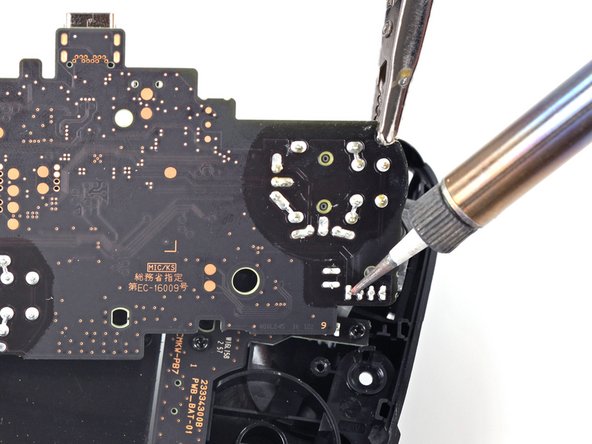
    • Desolder the rumble motor solder points on either side of the motherboard.

    • Remove the rumble modules.

    • Refer to the following solder guide if necessary: How to Solder

    • Solder the new rumble modules into the same pins.

  20. Switch Pro Controller Motherboard Replacement, Desolder the main power cable: 手順 20、 2の画像 1 Switch Pro Controller Motherboard Replacement, Desolder the main power cable: 手順 20、 2の画像 2
    • Remove the main power cable from the highlighted pins by de-soldering them.

    • Remove the motherboard.

    • Refer to the following solder guide if necessary: How to Solder.

終わりに

To reassemble your device, follow these instructions in reverse order.

4 の人々がこのガイドを完成させました。

作成者

4人の作成者と共同で作成されました。

Jared Murphy Johnson

メンバー登録日: 09/16/20

254 ポイント

1ガイドが承認済み

0 件のコメント

コメントを追加

統計データ:

過去 24時間: 10

過去 7 日: 71

過去 30 日: 337

今までの合計 13,858