はじめに
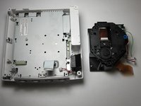
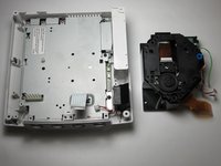
This guide details how to replace a failed GD-ROM drive with a new working drive.
Be sure to replace the GD-ROM with one corresponding to your model number. Refer to the Top Cover Disassembly Guide for instructions on where to find your model number.
Problem with this guide: The photos incorrectly show the power supply has been removed.
必要な工具と部品
-
-
Flip the console over on its back.
-
Take note of your model number, in case replacement parts are needed.
 FixBotに聞いてみる
-
-
-
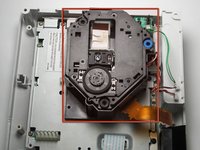
Remove the expansion bay by applying pressure to the small clip on the expansion bay while prying it away from the console.
-
-
-
Locate and remove all four black 12mm Phillips #02 screws from the underside of the console.
-
-
-
Turn the console right side up.
-
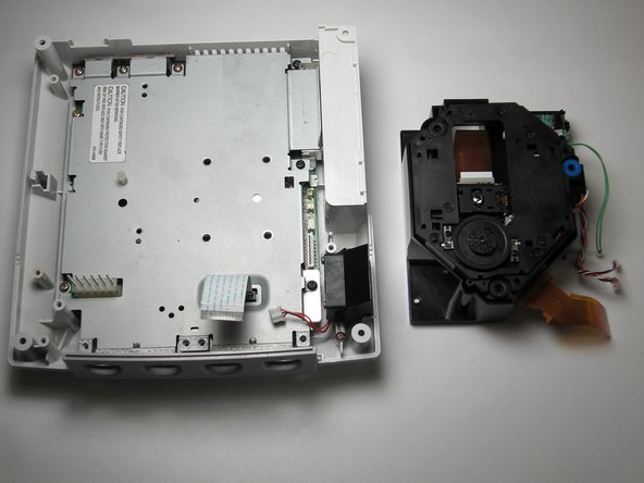
Remove the top cover by gently lifting the upper portion of the console.
-
-
-
-
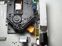
Detach the orange cable by giving it a gentle pull while wiggling the cable back and forth until it loosens from the logic board.
-
-
-
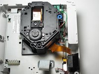
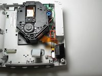
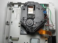
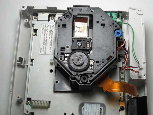
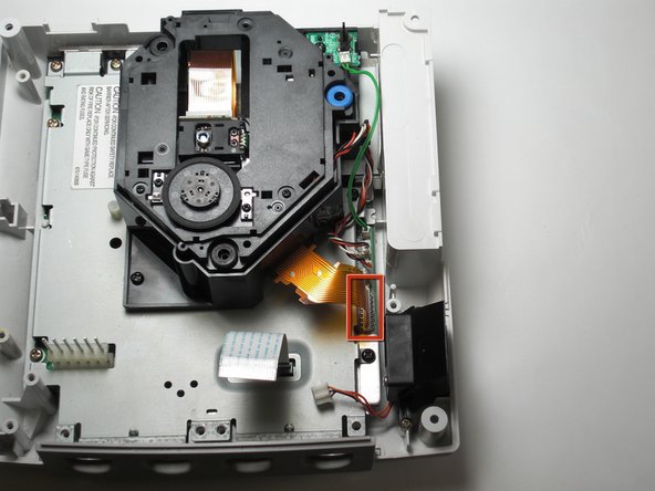
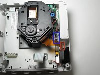
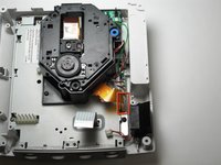
Detach the cables by gently pulling the three GD-ROM cables to remove them from the logic board.
-
-
-
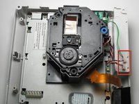
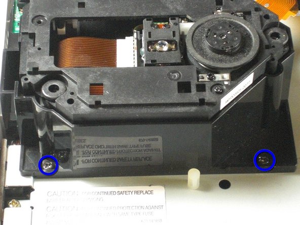
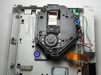
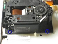
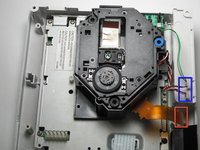
Remove the two black 12mm Philips #02 screws located on the left side of the GD-ROM bracket.
-
-
-
Connect the three GD-ROM cables to the logic board.
-
Connect the GD-ROM data ribbon to the logic board.
-


10 の人々がこのガイドを完成させました。
チーム

Cal Poly, Team 5-1, Regan Fall 2009 Cal Poly, Team 5-1, Regan Fall 2009人のメンバー
CPSU-REGAN-F09S5G1
5 メンバー
37のガイドは作成済み
2件のガイドコメント
If only it was that simple Sega screwed U.K gamers over with the fact we have to buy totally new consoles due to the wires of the disk drive being soldered in rather than clipped in.
My HKT-3020 console, NTSC-U revision 1, manufactured in Japan during 4/2000, does not have the orange cable shown in step 5. I was able to skip steps 5 and 6, and for step 7 I had to remove 3 screws, not 2. My GD-ROM drive came as an assembly, mounted on a metal plate; the entire assembly simply lowers into a connector port. After removing the screws, I just had to gently wiggle it up and out of the port, then lower the replacement assembly into the same port, and replace the 3 screws.