メインコンテンツにスキップ

このバージョンは誤った内容を含んでいる可能性があります。最新の承認済みスナップショットに切り替えてください。

必要条件のみ
この修理ガイドは、他のガイドの前提条件として使用されます。それ自体は不完全で、単独で使用されることはありません。

必要な工具と部品

  1. , バックカバー: 手順 1、 1の画像 1
    • スマートフォンの電源を切ります。

    • Note8の裏面に留められた接着剤を柔らかくするために、iOpenerを用意します

    • 電源ボタンの側面に沿って、Note8の裏面にiOpenerを置きます。

  2. : 手順 2、 3の画像 1 : 手順 2、 3の画像 2 : 手順 2、 3の画像 3
    • 吸盤ハンドルを使ってバックカバーを持ち上げて、生じた隙間に開口ピックを差し込みます。

    • バックカバーはわずかにエッジがカーブしているため、開口ピックを下側から低い角度で差し込んでください。

    • デバイス横の中央部分から作業を始めて、吸盤ハンドルを引き上げながら、ピックで接着剤を切開します。

    • 開口ピックをテコのように大きく動かしすぎないでください。バックカバーを破損することがあります。吸盤ハンドルを引き上げながら、開口ピックをスライドして接着剤を切開します。

    • 開口ピックを下側コーナーに向けて動かし、接着剤がケースに再装着しないよう、その場に残しておきます。

    • 別の開口ピックを使って上部コーナーまで移動します。

    • ここに翻訳を挿入する

  3. この手順は未翻訳です。 翻訳を手伝う。

    : 手順 3、 3の画像 1 : 手順 3、 3の画像 2 : 手順 3、 3の画像 3
    • Again take another opening pick and carefully move it around the corner and along the top edge.

    • Reheat with an iOpener if necessary.

    • Leave the pick at the top right corner to keep the adhesive from resealing.

  4. この手順は未翻訳です。 翻訳を手伝う。

    : 手順 4、 3の画像 1 : 手順 4、 3の画像 2 : 手順 4、 3の画像 3
    • Rotate the device and start to separate the adhesive at the bottom with another opening pick.

    • Leave the pick at the bottom right corner to keep the adhesive from resealing.

  5. この手順は未翻訳です。 翻訳を手伝う。

    : 手順 5、 3の画像 1 : 手順 5、 3の画像 2 : 手順 5、 3の画像 3
    • When the adhesive has been separated on all three sides properly you will be able to slowly lift the back cover.

    • Don't force it open. Use an iOpener to again soften the adhesive if the back cover won't come off or starts to bend.

    • Pay attention to the fingerprint sensor connector when flipping the back cover open. You might need to disconnect it as described in the next step.

  6. : 手順 6、 1の画像 1
    • ピンセットを使って、指紋センサーの接続を外します。

    • コネクタは、バックカバーをパカッと開いたときにすでに外れているかもしれません。

  7. : 手順 7、 1の画像 1
    • バックカバーを取り外します。

    • 再組み立ての準備をするには、スマートフォンに残った接着剤を取り除き、イソプロピルアルコールと糸くずの出ない布で接着剤の箇所を拭き取ってください。

  8. : 手順 8、 1の画像 1
    • #00プラスネジを10本外します。

  9. : 手順 9、 2の画像 1 : 手順 9、 2の画像 2
    • 開口ピックの上端を、NFCアンテナおよび充電コイルアセンブリとケースの間に差し込みます。

    • ケースからアセンブリ上部を持ち上げます。

  10. : 手順 10、 1の画像 1
    • 充電コイル全体とNFCアンテナアセンブリを注意深く引き上げます。

    • アセンブリの左下部分は、フレームにわずかに接着されています。

  11. , バッテリーの接続を外す: 手順 11、 1の画像 1
    • スパッジャーの平面側先端を使って、バッテリーコネクタの接続を外します。

  12. この手順は未翻訳です。 翻訳を手伝う。

    : 手順 12、 1の画像 1
    • Prepare an iOpener and apply it to the display for at least two minutes to loosen the adhesive beneath the battery. Reheat and reapply the iOpener as needed.

    • Alternatively or when the battery is blown up, you can apply some isopropyl alcohol under each corner of the battery and allow it to penetrate for several minutes to help weaken the adhesive.

  13. この手順は未翻訳です。 翻訳を手伝う。

    : 手順 13、 2の画像 1 : 手順 13、 2の画像 2
    • Use the flat end of a spudger to pry up the battery from the top right corner.

    • You will be prying against the case directly above the mainboard. Pry carefully to avoid damaging any close components.

    • You may need to reheat and reapply the iOpener repeatedly to further soften the adhesive. The adhesive is tough and it may take a few tries to get the spudger started under the battery.

    • Use the spudger to pry up the battery until you can insert an opening pick to prevent the adhesive from resealing.

    • Try your best not to deform the battery during this process. Soft-shell lithium-ion batteries can leak dangerous chemicals, catch fire, or even explode if damaged. Do not use excessive force or pry at the battery with metal tools.

  14. この手順は未翻訳です。 翻訳を手伝う。

    : 手順 14、 3の画像 1 : 手順 14、 3の画像 2 : 手順 14、 3の画像 3
    • Use the flat end of the spudger to pry up the top left corner of the battery where the flex cable is located.

    • Slide the spudger along the side of the battery to break apart remaining adhesive.

    • When prying keep to the areas marked orange. Avoid the red area in the middle which is the back of the display.

  15. この手順は未翻訳です。 翻訳を手伝う。

    : 手順 15、 1の画像 1
    • Lift the battery out of the case.

    • Do not reuse the battery after it has been removed, as doing so is a potential safety hazard. Replace it with a new battery.

    • Remove any remaining adhesive from the phone, and clean the glued areas with isopropyl alcohol and a lint-free cloth.

    • Follow this guide to install battery adhesive.

    • Follow this guide to install custom-cut adhesives.

  16. この手順は未翻訳です。 翻訳を手伝う。

    : 手順 16、 2の画像 1 : 手順 16、 2の画像 2
    • Insert a SIM card opening tool into the small hole on the left side of the top edge of the phone.

    • Press to eject the tray.

    • Remove the SIM card tray from the phone.

  17. この手順は未翻訳です。 翻訳を手伝う。

    : 手順 17、 1の画像 1
    • Remove the six Phillips #00 screws on the loudspeaker assembly at the bottom of the phone.

  18. この手順は未翻訳です。 翻訳を手伝う。

    : 手順 18、 2の画像 1 : 手順 18、 2の画像 2
    • Use the flat end of a spudger to pry up the loudspeaker assembly.

    • You will be prying above the mainboard and the antenna cable. Pry carefully to avoid damaging any close components.

    • Remove the loudspeaker assembly.

  19. この手順は未翻訳です。 翻訳を手伝う。

    : 手順 19、 2の画像 1 : 手順 19、 2の画像 2
    • Remove the two coax cables running from the daughterboard to the motherboard.

    • If you want to replace your display assembly with frame it is not absolutely necessary to remove the coax cables. However we advise to do so to avoid damage or tension on them.

    • Use a pair of tweezers to carefully disconnect both ends of the white coax cable and remove it.

  20. この手順は未翻訳です。 翻訳を手伝う。

    : 手順 20、 2の画像 1 : 手順 20、 2の画像 2
    • Use a pair of tweezers to carefully disconnect both ends of the blue coax cable and remove it.

  21. この手順は未翻訳です。 翻訳を手伝う。

    : 手順 21、 2の画像 1 : 手順 21、 2の画像 2
    • Use the flat end of a spudger to disconnect both the display and the touchscreen cables.

  22. この手順は未翻訳です。 翻訳を手伝う。

    : 手順 22、 2の画像 1 : 手順 22、 2の画像 2
    • Use the flat end of a spudger to disconnect the power button flex cable.

    • Disconnect the flash and proximity sensor cable.

  23. この手順は未翻訳です。 翻訳を手伝う。

    : 手順 23、 2の画像 1 : 手順 23、 2の画像 2
    • Use the flat end of a spudger to disconnect the flex connector of the front facing camera.

    • Carefully remove the front facing camera with a pair of tweezers.

  24. この手順は未翻訳です。 翻訳を手伝う。

    : 手順 24、 2の画像 1 : 手順 24、 2の画像 2
    • Use the flat end of a spudger to disconnect the flex connector of the iris scanner.

    • Carefully remove the iris scanner with a pair of tweezers.

  25. この手順は未翻訳です。 翻訳を手伝う。

    : 手順 25、 1の画像 1
    • Remove the five Phillips #00 screws that hold down the motherboard, daughterboard, headphone jack and the charging port.

  26. この手順は未翻訳です。 翻訳を手伝う。

    : 手順 26、 2の画像 1 : 手順 26、 2の画像 2
    • Use the flat end of a spudger to disconnect the headphone jack flex connector.

    • Carefully remove the headphone jack with a pair of tweezers.

  27. この手順は未翻訳です。 翻訳を手伝う。

    : 手順 27、 2の画像 1 : 手順 27、 2の画像 2
    • Prepare an iOpener and apply it to the bottom part of the phone to loosen the adhesive beneath the microphone flex cable.

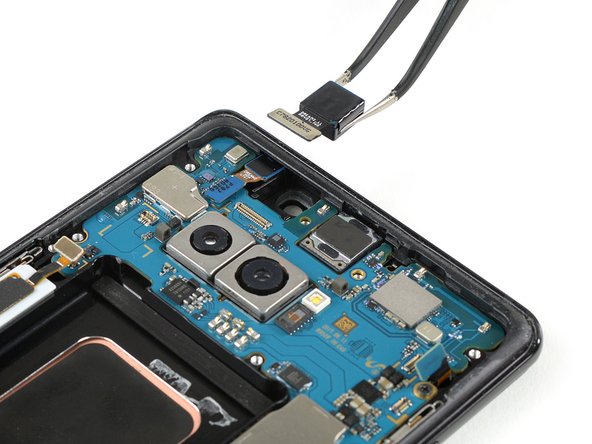
    • Use a pair of tweezers to carefully lift the microphone out of its recess and loosen it from the mid frame.

    • Do not remove the microphone. It is still attached to the daughterboard.

  28. この手順は未翻訳です。 翻訳を手伝う。

    : 手順 28、 2の画像 1 : 手順 28、 2の画像 2
    • It is possible to remove the motherboard whilst keeping the daughterboard in its place. However the flex connector of the daughterboard sits on the backside of the motherboard and it's a bit of a fumbling to disconnect it while you're holding the motherboard in your hand.

    • In case you're planning to remove the motherboard without the daughterboard take especially care not to damage any surrounding components whilst disconnecting the flex cable.

    • Use the pointed end of a spudger to pry up the motherboard until you can get a good grip.

    • The motherboard sits loosely on the mid frame so there are different positions to place the spudger and to pry it up. Avoid to damage any surrounding components.

  29. この手順は未翻訳です。 翻訳を手伝う。

    : 手順 29、 3の画像 1 : 手順 29、 3の画像 2 : 手順 29、 3の画像 3
    • Carefully lift up the motherboard.

    • To lift the daughterboard out of its recess pull both components slowly towards the upper end of the phone whilst lifting upwards.

ゴール

作成者

2人の作成者と共同で作成されました。

Dominik Schnabelrauch

メンバー登録日: 11/23/16

203,353 ポイント

682のガイドは作成済み

チーム

iFixit iFixit人のメンバー

Staff

135 メンバー

16,817のガイドは作成済み

0 件のコメント

コメントを追加

統計データ:

過去 24時間: 0

過去 7 日: 1

過去 30 日: 1

今までの合計 74