はじめに
The following guide will help you take apart the control box, remove, and replace the motherboard of the Oculus Rift DK1. Replacing the motherboard may be necessary because your motherboard is 'fried.' For further investigation, refer to the Oculus Rift Troubleshooting Guide. Replacing the motherboard should be a last resort.
必要な工具と部品
-
-
-
Use a plastic opening tool to carefully pry off the four rubber feet from the control box.
-
You have now revealed the four 9 mm Phillips #1 screws underneath the rubber feet.
 FixBotに聞いてみる
-
-
-
Use a Phillips #1 Screwdriver to unscrew the four 9mm Phillips screws on the bottom of the control box.
-
You can now remove the bottom lid of the control box. It should come apart easily.
-
-
-
-
-
-
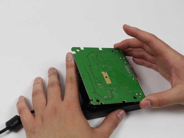
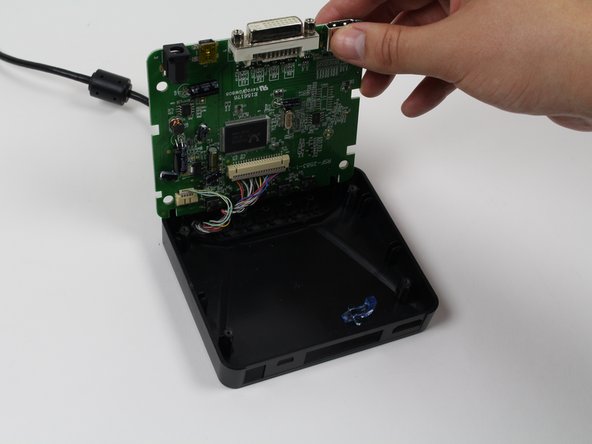
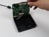
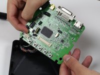
Use your finger(s) to start lifting the motherboard from the control box casing. While doing so, use your other hand to push the DVI connector into the control box casing.
-
When the DVI connector has cleared the casing, lift the motherboard.
-
-
-
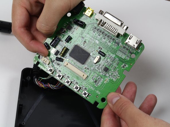
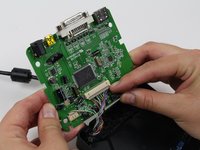
Use a plastic opening tool or your fingernails to disconnect the grey wire connectors. To make removal easier, pry the left and right edges to carefully remove the connector.
-
Do so for both of the wires attached to the motherboard.
-
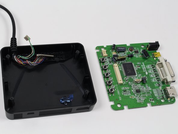
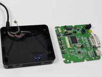
Now fully separate the motherboard from the control box casing.
-
-



To reassemble your device, follow these instructions in reverse order.
チーム

Cal Poly, Team 70-5, Forte Winter 2015 Cal Poly, Team 70-5, Forte Winter 2015人のメンバー
CPSU-FORTE-W15S70G5
4 メンバー
18のガイドは作成済み
