はじめに
If you can no longer charge your Logitech G733 headset and you've ruled out a faulty battery, the charging port may need to be replaced. Accessing the power button requires taking off the circuit board, you can also access many other components with these same steps. For this guide, you will need a Phillips #000 screwdriver, a T4 Torx screwdriver, and a soldering iron. This is a difficult replacement. Soldering experience is advised.
必要な工具と部品
-
-
Gently begin to pull the left ear pad off, starting from the top.
-
Slide your finger around the edges until it releases entirely.
 FixBotに聞いてみる
-
-
-
Remove the four securing the speaker housing with the T4 Torx screwdriver.
-
Lift the speaker housing away from the chassis, with care not to strain the connected speaker cable.
-
-
-
-
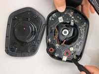
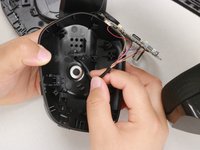
Remove the screw on the bottom right-hand side of the headphone using a Phillips #00 screwdriver.
-
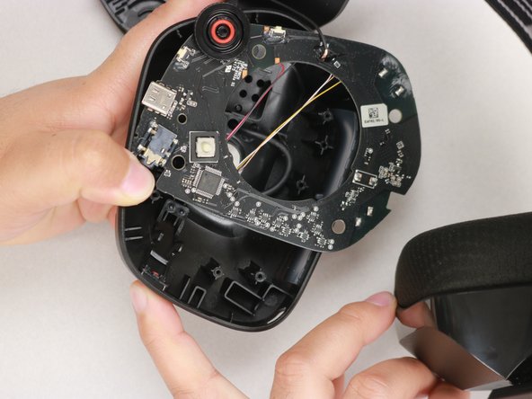
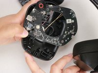
Use your thumb to gently pull back the tab at the upper right-hand corner of the headphone and simultaneously pull the motherboard out.
-
-
-
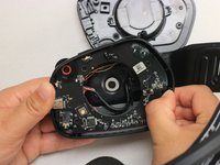
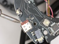
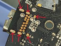
Using the soldering iron, apply heat to three pins on one side and wiggle the port free from the melted pool of solder.
-
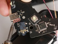
Repeat for the opposite side.
-


To reassemble your device, follow these instructions in reverse order.
3 の人々がこのガイドを完成させました。

チーム

Western Carolina University, Team 1-5, Virtue Spring 2023 Western Carolina University, Team 1-5, Virtue Spring 2023人のメンバー
WCU-VIRTUE-S23S1G5
4 メンバー
18のガイドは作成済み
3件のガイドコメント
Where did you get the spare USB Port from?
The closest match is TE Connectivity 2338792-1 USB TYPE C 3.1 CONN REV TOP MOUNT CH1.6
James Powers - 返信 共有
2338792-1 has diffrient similar casing but diffrient pin configuration and also less pins (12), should have 14 pins. Just contacted Logitech support but they didn't want to tell me the part number. If anyone knows how to get that port, please let us know.