はじめに
The trigger assembly on the Flydigi Apex 4 is responsible for detecting analog input when the trigger is pressed. Over time, the trigger mechanism may wear out or become damaged, resulting in inconsistent inputs, a lack of response, or a trigger that feels physically loose. This guide will walk you through safely removing and replacing the trigger assembly. Before beginning the repair, ensure the controller is powered off and unplugged.
必要な工具と部品
-
-
Ensure the controller is fully powered off before beginning.
-
Disconnect the USB-C cable if the controller is plugged in.
-
Remove any wireless adapter or dongle connected to your device.
 FixBotに聞いてみる
-
-
-
Remove the button caps and the magnetic faceplate of the controller.
-
Use a Phillips #00 screwdriver to remove the four screws securing the front of the controller to the frame.
-
-
-
-
Insert a plastic opening tool into the seam between the front and back shell along the bottom edge of the controller.
-
Gently run the opening tool along the seam to release the plastic clips holding the two halves together.
-
Work your way around all edges until the back shell is fully unclipped.
-
Carefully lift the back shell away from the front half and set it aside.
-
-
-
With the controller open, identify the trigger assembly on the side you are replacing.
-
-
-
Use a spudger or your fingernail to gently flip up the locking tab on the connector linking the trigger assembly to the main PCB.
-
Carefully pull the ribbon cable straight out of the connector.
-
-
-
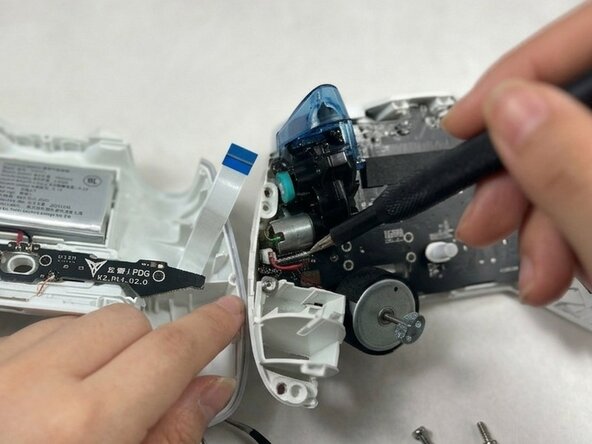
Use a Phillips #00 screwdriver to remove the screws securing each trigger assembly.
-
Lift the trigger assembly straight up and out of the controller frame.
-


To reassemble your device, follow these instructions in reverse order. Take your e-waste to an R2 or e-Stewards certified recycler.

チーム

UMass Dartmouth, Team 3-1, Shaddix Spring 2026 UMass Dartmouth, Team 3-1, Shaddix Spring 2026人のメンバー
UMASSD-SHADDIX-S26S3G1
3 メンバー
2のガイドは作成済み