この翻訳は機械によって生成されたものであり、まだ人間による校正は行われていません。 日本語を話せますか? レビューはこちらから。
はじめに
モーターが動作しない、またはフルパワーでしか動作しない場合は、トライアックが故障しています。
必要な工具と部品
-
-
-
まずプラグを抜き、ケーブルを巻き取ります。バキュームホースの接続を外します。本体を開きます。
-
PH2のネジが4本あります。
-
これらのネジはすべて同じ長さです。
 FixBotに聞いてみる
-
-
-
手順2の2つ目のクリップを確認してください。
-
引き抜いてください。
-
開きます。そこにある白いケーブルと青いケーブルを取り外してください。
-
青いケーブルと白いケーブルはコネクタのサイズが異なります。正しい向きでしか取り付かないようになっています。
-
-
-
タービンを引っ張ります。ゴム製のケースが引っかかっていますが、そのまま強く引っ張ってください。
-
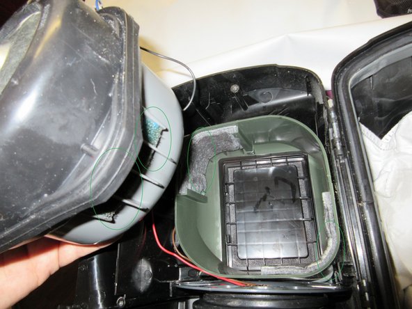
次に、灰色のプラスチック部品を再び引っ張ります。フィルターを確認してください。再組み立て時にフィルター同士が向かい合うようにする必要があります!!!(緑色の円でマークされています)
-
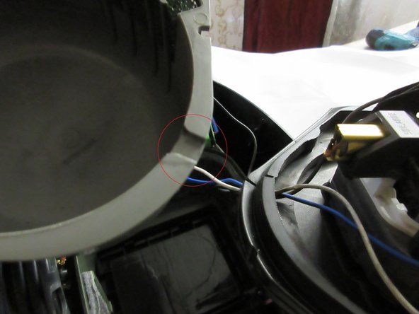
赤色の円を確認してください。切り欠きがあります。そこが、白いケーブル、青いケーブル、および黒いケーブルがハウジングを通る場所です。
-
-
-
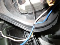
白いケーブルと青いケーブルの詳細。プラグには小さなスプリングホルダーが付いています。押しながら引き抜いてください。
-
プラグはそれぞれサイズが異なります。
-
モーターの短い黒いケーブルの接続を外します。プラグには同様にスプリングが付いているので、押しながら黒いケーブルを引き抜いてください。
-
-
-
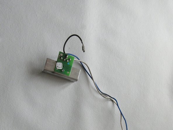
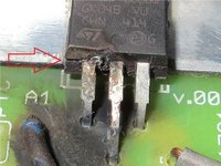
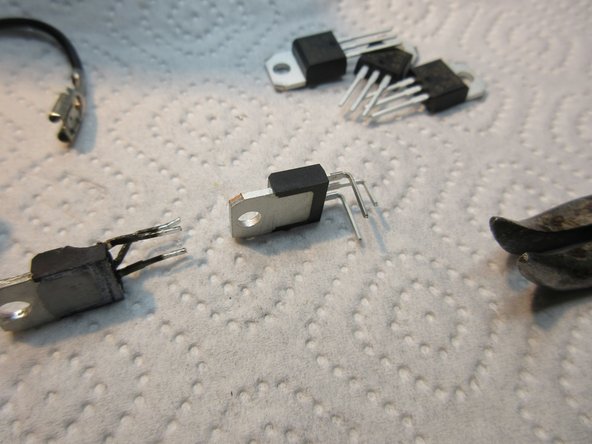
これで全てです。ケーブルとアルミ製冷却材が付いた、焼け焦げて破損したトライアックです。
-
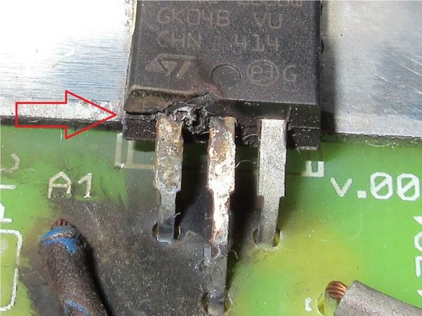
赤矢印を見てください。ハウジングの箇所で破損しています。ピンがハウジングの根本で曲がっているため、この破損はトライアックの取り付け時に発生したものです。非常に残念です。電流により爆発し、完全に損傷してしまいました。
-
ケーブルは問題ないようで、基板も無事です。焦げているように見えますが、これは黒い煤(すす)が付着しているだけです。
-
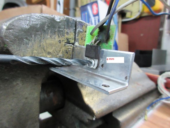
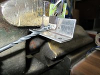
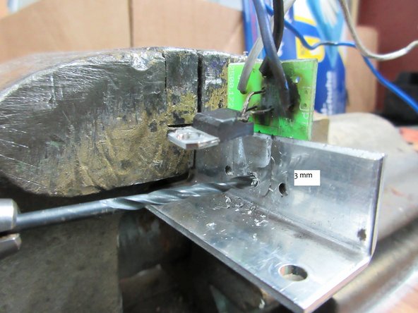
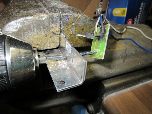
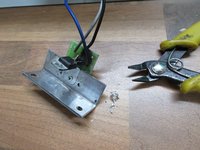
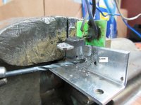
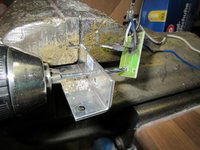
それでは、この部品をドリルで取り外します。
-
-
-
この手順で使用する道具:Desoldering Pump$3.99
-
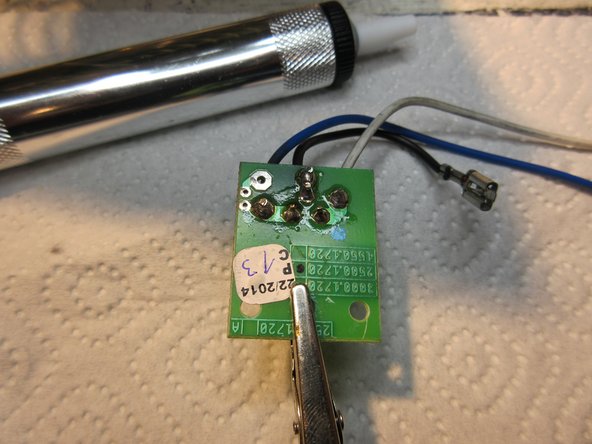
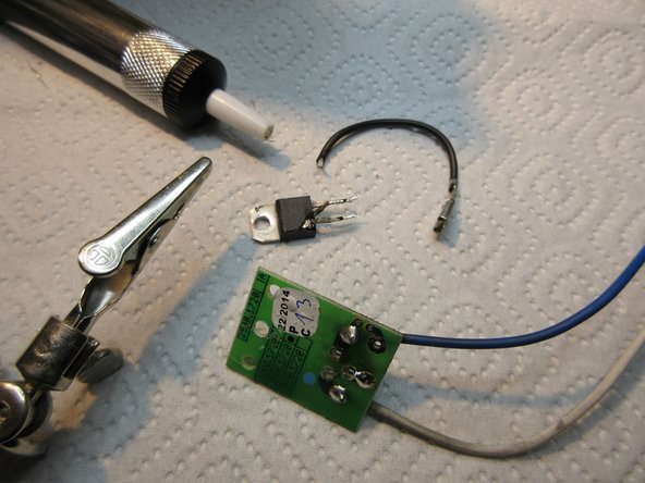
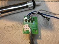
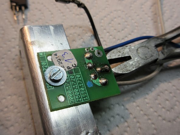
次に、はんだを取り除きます。基板には、アルミニウム製ヒートシンクに適合する2つの穴があります。
-
吸取線ポンプを使えば簡単です。
-
-
-
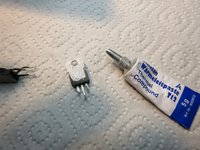
熱伝導グリスを少量取ります。ごくわずかな量で十分です。
-
M3ネジとM3ワッシャーを取り、アルミニウム部品に固定します。
-
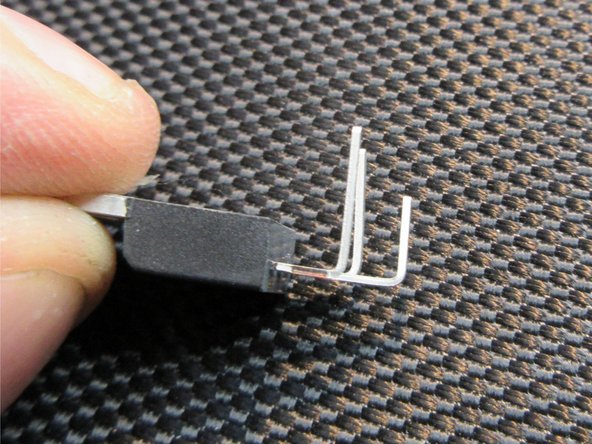
機械的な応力を加えた後、新しい部品をはんだ付けします。
-
-
-
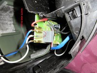
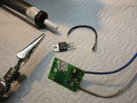
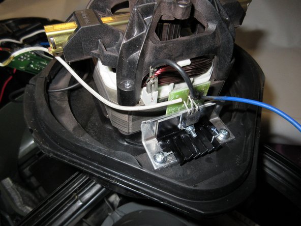
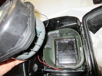
次に白と青のケーブルを配置します。長い黒のケーブルももう1本あります。
-
切り欠きを確認し、正しく収まるようにします。
-
フィルターが正しく取り付けられていることを確認してください。
-
-
-
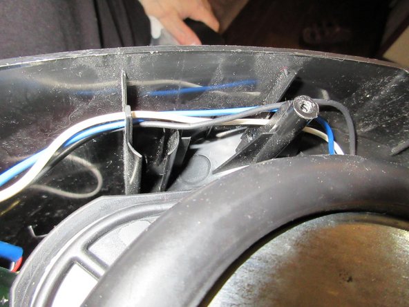
ケーブルの細部。
-
ケーブルを固定するための切り欠きがあります。
-
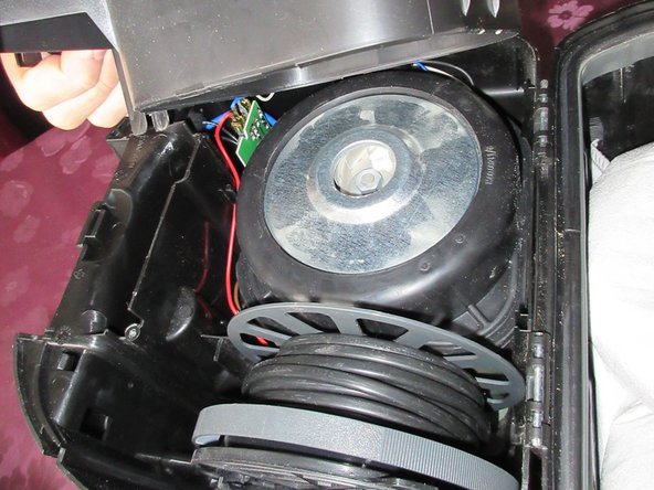
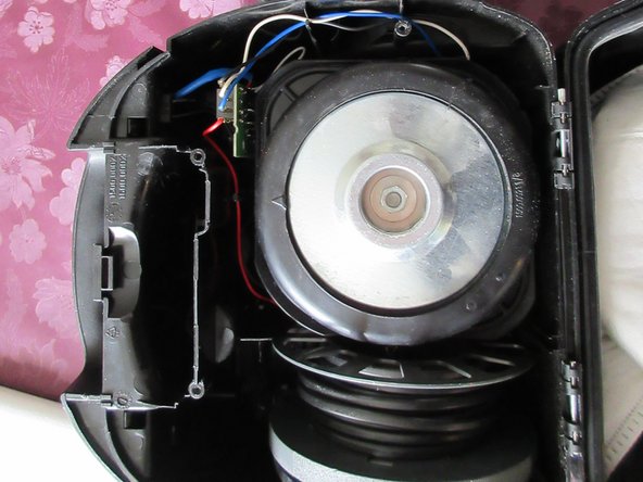
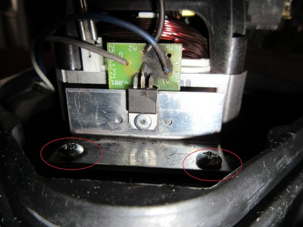
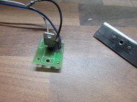
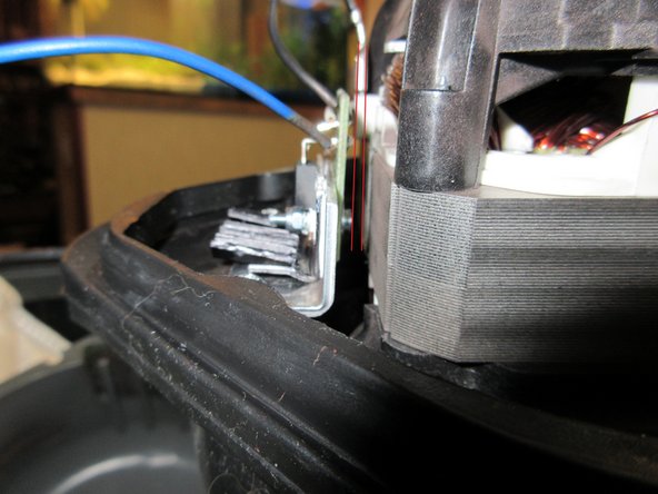
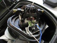
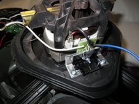
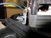
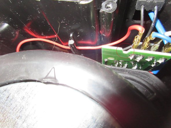
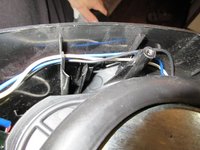
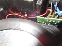
3枚目の写真の基板にある大きな切り欠きを確認してください。赤丸で囲った部分です。このパーツを閉じるとき、ハウジングのラッチがこの切り欠きにはまります。手順1から4で、ラッチ、切り欠き、クリップの扱いに注意すべき箇所を確認してください。
-
-
-
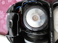
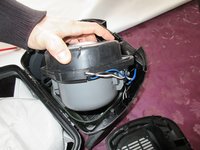
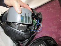
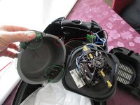
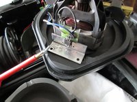
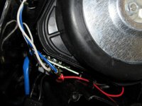
すべてのパーツが均等に収まり、ラッチ、ノッチ、クリップがすべて噛み合った状態でハウジングをしっかりと押し下げてから、4本の長いネジを慎重に締め直してください。
-
動作確認をして完了です。お疲れ様でした。
-
:D
-
短い説明で申し訳ありません。英語は得意ではありませんが、写真が助けになれば幸いです。
-
-




















逆の手順でデバイスを組み立て直します。
4 の人々がこのガイドを完成させました。

5件のガイドコメント
Well, my child played with that Vacuum-cleaner and it overheated.
So I had to do this repairmanual for you.
Do not let play children with Machines. ;)
Schwarzstein - 返信 共有
Just some comments for English speakers. I'm not dealing with spelling or awkward phrasing - I think it's clear emough. But for those that aren't sure on certain words, maybe this will help.
First tool listed is a #2 Philips-head screwdriver. So when you see PH2 screws, use your phillips screwdriver (also known as a cross screwdriver in some parts of the English-speaking world).
Step 2, middle bullet - "Pull, it knacks" literally would be cracks, which might sound negative. So "Pull, it does separate."
Step 4 (and elsewhere): turbine or motor.
Step 6, 1st bullet (& see Step 9 and elsewhere for variations) - (aluminium-)cooling or cooler = (aluminum) heat sink. [Americans don't use the 2nd i of aluminium.]
Step 6 (and elsewhere), 3rd bullet: platine = printed circuit board (I'll always refer to it as the PCB).
Part 2 of notes comes in my next comment --
Part 2 of notes here --
Step 6, 2nd bullet [I know, out of order, but I wanted to use PCB, so translated it first] - Instead of translating it "The pins are bent directly at the housing, so this destruction occured at the montage of the triac !" I would've said "The pins are bent to go into the PCB, and the destructive forces inside the triac caused the assembly ("montage") to burst open at the other end of the pins, where they enter the triac housing!"
Steps 7-8 - there is a rivet that goes through the triack, then through the heat sink, then through the PCB. For getting the rivet out, you drill with a 4mm drill bit through the rivet head, through the triac mount, and lift the triac out of the way, then continue very carefully through the heat sink. Now the PCB can be removed from the heat sink. Then switch to a 3mm bit and drill the remnants of the rivet out of the PCB.
Part 3 coming up --
Part 3 of 3 here
Step 10 - "follow the steps like on the pictures, i can't explain it, sorry. Like on the pictures, you can see, do it too" becomes "Follow the pictures in steps 4-10, especially step 6 and step 10. Pins 1 and 3 get bent closer to the triac, pin 2 (the middle pin) gets bent further out ('longer') from the triac, to fit the wholes in the PCB.
Step 11, 1st bullet - use less thermal grease/compund than is shown in the picture of step 11. He said "little" and that was correct.
Step 11, 2nd bullet - Instead of riveting (if you aren't good at it you might break the PCB), he replaces it with a bolt, washer, and nut. Tighten it - but not so much you break the PCB.
Starting Step 13, you're reassembling. His CONCLUSION at the end says to do the steps in reverse order to finish - maybe he later added steps 13 to the end later and didn't remove that statement.
Step 17 Jägermeister = hunt master -- go hunting things to vacuum up?
