メインコンテンツにスキップ
リペアコミュニティに参加 - アカウントの作成

Accessing Logicboard

必要な工具と部品

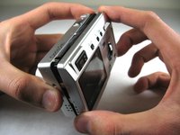
    1. Accessing Logicboard, Front and Back Cover: 手順 1、 2の画像 1 Accessing Logicboard, Front and Back Cover: 手順 1、 2の画像 2
      • Remove the following screws:

      • Two silver 3.15mm Phillips #00 screws on the right side of the camera

      • Two silver 2.08mm Phillips #00 screws on the left side of the camera

      FixBotに聞いてみる

      コメントを追加

    2. Accessing Logicboard: 手順 2、 1の画像 1
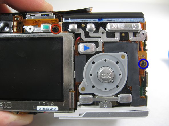
      • Remove the two indicated screws on the bottom of the camera:

      • The screw circled in red is a longer silver 3.15mm Phillips #00 screw

      • The screw circled in blue is a shorter silver 2.25mm Phillips #00 screw

      FixBotに聞いてみる

      コメントを追加

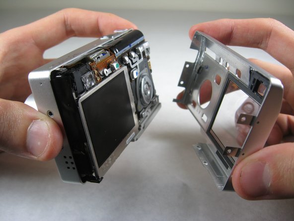
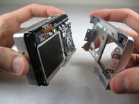
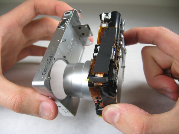
    3. Accessing Logicboard: 手順 3、 2の画像 1 Accessing Logicboard: 手順 3、 2の画像 2
      • Carefully pull the back of casing away from the front.

      FixBotに聞いてみる

      コメントを追加

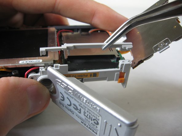
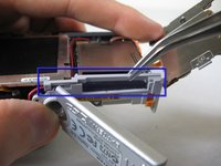
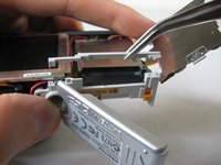
    4. Accessing Logicboard: 手順 4、 3の画像 1 Accessing Logicboard: 手順 4、 3の画像 2 Accessing Logicboard: 手順 4、 3の画像 3
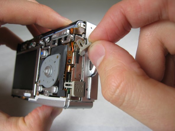
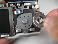
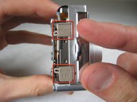
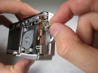
      • After removing the back cover, several things must be removed.

      • Silver donut-shaped button will fall off. Place separately. Remove the plug covers on the right side of camera, labeled “PC/AV” and “DC IN 4.5V”.

      FixBotに聞いてみる

      コメントを追加

    5. Accessing Logicboard: 手順 5、 2の画像 1 Accessing Logicboard: 手順 5、 2の画像 2
      • To remove the front cover, gently hold the inside structure of the camera and slowly pull the front cover off.

      FixBotに聞いてみる

      コメントを追加

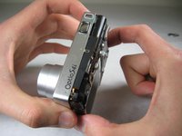
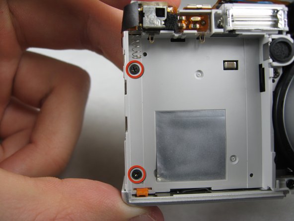
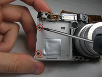
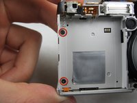
    1. Accessing Logicboard, Logicboard: 手順 6、 2の画像 1 Accessing Logicboard, Logicboard: 手順 6、 2の画像 2
      • On the front of the camera, in battery case, remove screws indicated:

      • Two black 2.05mm Phillips #00 screws

      FixBotに聞いてみる

      コメントを追加

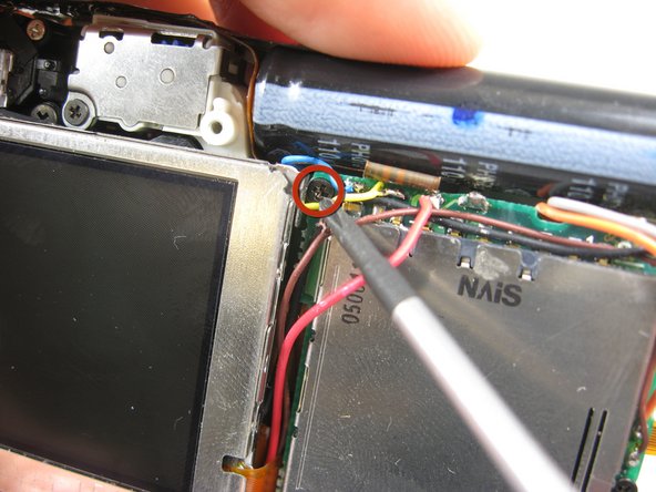
    2. Accessing Logicboard: 手順 7、 2の画像 1 Accessing Logicboard: 手順 7、 2の画像 2
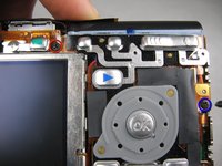
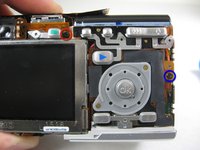
      • Flip the camera over to the backside and remove screws indicated:

      • The screw circled in red is a longer black 3.00mm Phillips #00 screw

      • The screw circled in blue is a shorter black 2.00mm Phillips #00 screw

      FixBotに聞いてみる

      コメントを追加

    3. Accessing Logicboard: 手順 8、 1の画像 1
      • Pull the cover plate off for the two power cord jacks.

      FixBotに聞いてみる

      コメントを追加

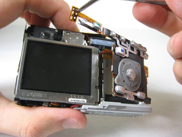
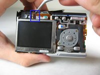
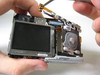
    4. Accessing Logicboard: 手順 9、 3の画像 1 Accessing Logicboard: 手順 9、 3の画像 2 Accessing Logicboard: 手順 9、 3の画像 3
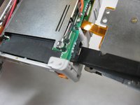
      • Cautiously and gently pull up the control board at the upper left corner, next to the viewfinder.

      FixBotに聞いてみる

      コメントを追加

    5. Accessing Logicboard: 手順 10、 1の画像 1
      • Remove the orange tape on top of the SD cardholder.

      FixBotに聞いてみる

      コメントを追加

    6. Accessing Logicboard: 手順 11、 1の画像 1
      • Open the battery cover.

      FixBotに聞いてみる

      コメントを追加

    7. Accessing Logicboard: 手順 12、 2の画像 1 Accessing Logicboard: 手順 12、 2の画像 2
      • Lift the indicated plastic piece off.

      FixBotに聞いてみる

      コメントを追加

    8. Accessing Logicboard: 手順 13、 2の画像 1 Accessing Logicboard: 手順 13、 2の画像 2
      • Remove screws indicated:

      • Two black 4.80mm Phillips #00 screws

      FixBotに聞いてみる

      コメントを追加

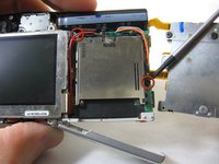
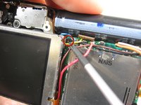
    9. Accessing Logicboard: 手順 14、 1の画像 1
      • Unsolder points indicated.

      • Please refer to steps 1 through 6 of the Ifixit soldering guide to unsolder these leads.

      FixBotに聞いてみる

      コメントを追加

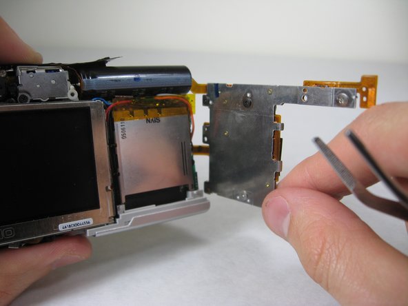
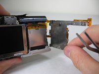
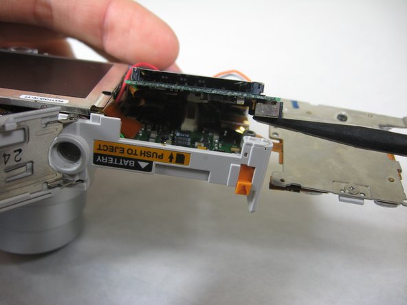
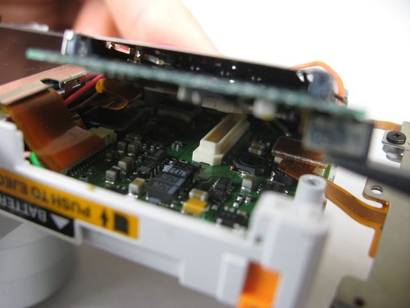
    10. Accessing Logicboard: 手順 15、 3の画像 1 Accessing Logicboard: 手順 15、 3の画像 2 Accessing Logicboard: 手順 15、 3の画像 3
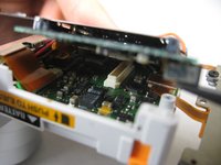
      • Carefully lift up SD cardholder to reveal logicboard.

      FixBotに聞いてみる

      コメントを追加

終わりに

To reassemble your device, follow these instructions in reverse order.

キャンセル: このガイドを終了できませんでした。

作成者

5人の作成者と共同で作成されました。

Nicole Wong

メンバー登録日: 01/30/11

371 ポイント

3のガイドは作成済み

チーム

Cal Poly, Team 4-29, Regan Winter 2011 Cal Poly, Team 4-29, Regan Winter 2011人のメンバー

CPSU-REGAN-W11S4G29

3 メンバー

15のガイドは作成済み

0件のガイドコメント

コメントを追加

統計データ:

過去 24時間: 0

過去 7 日: 11

過去 30 日: 36

今までの合計 1,997