メインコンテンツにスキップ

2.2 GHz (Turbo Boost使用時最大3.4 GHz), 2.5 GHz (Turbo Boost使用時最大3.7 GHz)もしくは2.8 GHz (Turbo Boost使用時最大4.0 GHz) L3キャッシュで6 MBのクアッドコアIntel Core i7プロセッサ

774回答 すべてを表示

A1398 MacBook Pro 15" Mid 2015 Missing pad on L4010

Hello,

I've recently figured out that for some reason my facetime camera is not working even after SMC or PRAM reset procedures.

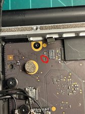
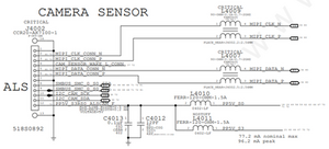
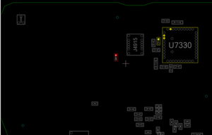
I was able to locate the problem and it was an L4010 chip near the backlight connector of the keyboard.

Due to my mistake, while I was working on the keyboard, I've accidentally connected the facetime camera connector while the battery is connected. I think this caused the problem.

To fix the issue, I was able to order the chip for L4010 which is FERR-120-ohm-1.5A from Digikey.

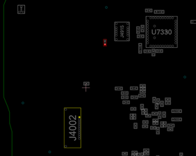
The problem is that due to the burnt L4010 chip, the PCB pad is missing, and need to find another place to solder the chip by jumping wire.

Is there any good place to put jumper wire for the chip?

I've included some ref photos for the boards.

Block Image

Block Image

Block Image

Block Image

回答がありました! 回答を表示 同じ問題があります

この質問は役に立ちましたか?

スコア 1
コメントを追加

2件の回答

ベストアンサー

@martini964 here you go. Contact 1 from L4010 to C7330 contact 1 for PP5V_S0 and L4010 pin 2 to pin 12 of J4002.

Block Image

このアンサーは役に立ちましたか?

スコア 5

5 件のコメント:

Thank you for your comment.

Is there any possibility this hard wiring can short other component in the future?

Also, what kind of wire are you recommending to use for this connection?

さんによる

No, it will not cause you any grief down the road. Use some thin insulated strand of wire. I use wires from an old LVDS ribbon cable but ultimately any thin copper wire will work. Just make sure you use some insulating paint on that wire/solder points after you soldered everything in places.

さんによる

@martini964 - I would use a small patching PCB board to mount the SMD device and mount it near where the part was then feed the wires to it PCB test board Cutting off a section of the board to the size you need.

What you don't want is the have any shorts to the ground plane that is surrounding the SMD's originals location.

さんによる

@oldturkey03

Thank you for your advice I've managed to wire two connection points with my home soldering kit.

I used some flux and 30 AWG wire for both connection points and put some electrical Kapton tape over it to secure it from vibrations for future use.

The process was not easy with the amazon soldering kit and bare wires but I was able to manage the wiring and the facetime camera is working perfectly now!

Thank you for you guys help!

さんによる

@martini964 good to hear you got it fixed. Job well done!

さんによる

コメントを追加

Ouch! This is not going to be easy ;-[

The inductor pads are located in the middle of the ground plane which is that large copper surface that surrounds it. At this point you’ll need to locate a point where you can solder patch wires. Using the boardview locate PPv5V_S3RSO_ALSCAM_F line (ALS contact #12) as well as PP5V_SO. Now solder the SMD onto the wire make sure the lines are as short as you can ands insulate them.

このアンサーは役に立ちましたか?

スコア 1

3 件のコメント:

Thank you for the comment.

If I have proper equipment to solder the patch I would do that. However, currently I don’t have any microscope or other precision equipment.

Is direct solder between other feed point is possible or patch need to be implemented for soldering?

I’m just worried if hard soldering between pins might short other component.

さんによる

The size of the exposed via line passing through the layers is not large enough to solder onto and physically connecting to the sub millimeter exposed point won't be strong enough.

Sorry, the limits here are physical you need to find another location to tie into.

Sounds like you've hit your tools and skills limit, see if you can find someone with the needed tools and skills to help you otherwise its time for a new logic board. Sorry ;-{

さんによる

Thank you for your advice I've managed to wire two connection points with my home soldering kit.

I used some flux and 30 AWG wire for both connection points and put some electrical Kapton tape over it to secure it from vibrations for future use.

The process was not easy with the amazon soldering kit and bare wires but I was able to manage the wiring and the facetime camera is working perfectly now!

さんによる

コメントを追加

回答を追加する

Martin Lee さん、ありがとうございました!
統計データ:

過去 24時間: 0

過去 7 日: 0

過去 30 日: 1

今までの合計 97