注意:あなたはさきほど閲覧しているガイドの前提となるページを編集しています。あなたが行った変更は、この手順を含むガイド全体に影響を与えます。
手順 4を翻訳中
手順4


-
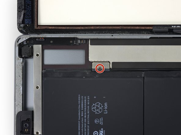
Remove the single 2.3 mm Phillips screw securing the battery connector to the logic board.
-
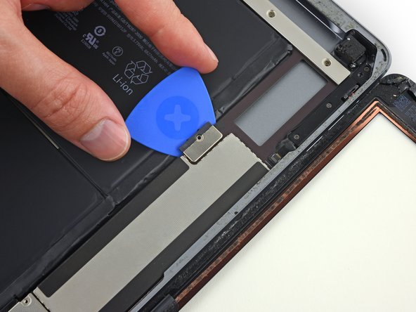
Slide the battery blocker underneath the battery connector area of the logic board, and leave it in place while you work.
クリエイティブコモンズのオープンソース著作権のもと、あなたの投稿は著作権の対象となります。