メインコンテンツにスキップ
リペアコミュニティに参加 - アカウントの作成

iHome iP21 Display LED Replacement

必要な工具と部品

    1. iHome iP21 Display LED Replacement, Base: 手順 1、 3の画像 1 iHome iP21 Display LED Replacement, Base: 手順 1、 3の画像 2 iHome iP21 Display LED Replacement, Base: 手順 1、 3の画像 3
      • Pry the four rubber feet from the bottom of the iP21 to expose four 11mm screws.

      • Unscrew the four 11mm screws from the base.

      • Pry the base loose using the spudger.

      • Remove the base by hand.

      FixBotに聞いてみる

      コメントを追加

    2. iHome iP21 Display LED Replacement, Housing: 手順 2、 2の画像 1 iHome iP21 Display LED Replacement, Housing: 手順 2、 2の画像 2
      • Remove the two black 6mm screws connecting the main circuit board to the housing top.

      • Gently pull front housing from the back housing.

      FixBotに聞いてみる

      コメントを追加

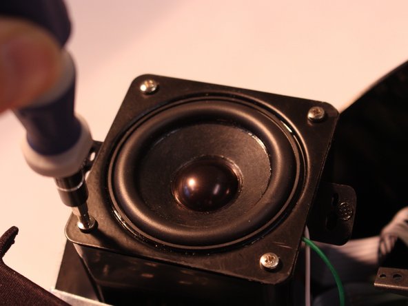
    1. iHome iP21 Display LED Replacement, Remove Speaker Assembly: 手順 3、 1の画像 1
      • Remove two 9mm screws holding speaker assembly in iP21, using iFixit Phillips #2 bit

      FixBotに聞いてみる

      コメントを追加

    2. iHome iP21 Display LED Replacement, Remove speaker from speaker assembly: 手順 4、 2の画像 1 iHome iP21 Display LED Replacement, Remove speaker from speaker assembly: 手順 4、 2の画像 2
      • Lift speaker assembly

      • Remove four 7mm screws to detach speaker from speaker assembly

      FixBotに聞いてみる

      コメントを追加

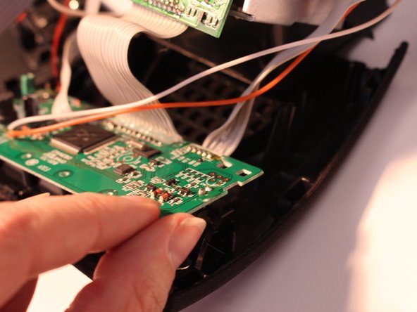
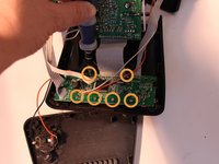
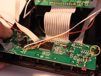
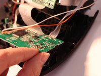
    1. iHome iP21 Display LED Replacement, Display circuit board: 手順 5、 3の画像 1 iHome iP21 Display LED Replacement, Display circuit board: 手順 5、 3の画像 2 iHome iP21 Display LED Replacement, Display circuit board: 手順 5、 3の画像 3
      • Remove six 6mm screws from display circuit board.

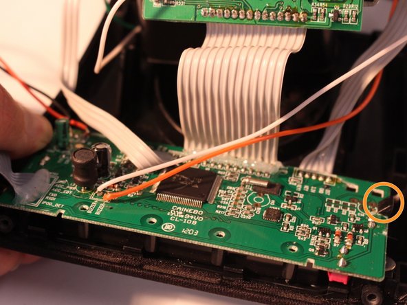
      • Press black holding clips down and outward to release display circuit board.

      • Lift display circuit board to detach it from the housing.

      FixBotに聞いてみる

      コメントを追加

    2. iHome iP21 Display LED Replacement, Cables: 手順 6、 2の画像 1 iHome iP21 Display LED Replacement, Cables: 手順 6、 2の画像 2
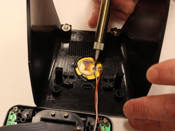
      • Desolder the solder joints connecting the grounding cable to the display circuit board.

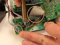
      • Remove glue from the ribbon cables with your fingers. Grasp and pull the glue to remove it from the circuit board.

      • Desolder the solder joints connecting the three ribbon cables to the back of the display circuit board.

      • Desolder the solder joints connecting the two grounding cables to the back of the display circuit board.

      • Desolder the solder joints connecting the two grounding cables to the back of the main housing.

      FixBotに聞いてみる

      コメントを追加

終わりに

To reassemble your device, follow these instructions in reverse order.

キャンセル: このガイドを終了できませんでした。

作成者

3人の作成者と共同で作成されました。

Brandy

メンバー登録日: 10/27/14

601 ポイント

6のガイドは作成済み

チーム

Eastern Washington University, Team 1-2, Carnegie Fall 2014 Eastern Washington University, Team 1-2, Carnegie Fall 2014人のメンバー

EWU-CARNEGIE-F14S1G2

6 メンバー

18のガイドは作成済み

0件のガイドコメント

コメントを追加

統計データ:

過去 24時間: 0

過去 7 日: 2

過去 30 日: 15

今までの合計 552