メインコンテンツにスキップ

このバージョンは誤った内容を含んでいる可能性があります。最新の承認済みスナップショットに切り替えてください。

必要な工具と部品

  1. この手順は未翻訳です。 翻訳を手伝う。

    : 手順 1、 3の画像 1 : 手順 1、 3の画像 2 : 手順 1、 3の画像 3
    • The left stick is the most common one to go bad.

    • Depress the battery release button on the top of the controller. Remove the battery holder from the controller.

    • Use tweezers or similar instrument, to peel the barcode sticker from the battery compartment.

  2. この手順は未翻訳です。 翻訳を手伝う。

    : 手順 2、 3の画像 1 : 手順 2、 3の画像 2 : 手順 2、 3の画像 3
    • Remove the seven 9.3 mm T8 Security Torx screws securing the rear case to the front case.

    • Insert a plastic opening tool between the front and rear cases along the left edge of the controller. Rotate the tool toward the front of the controller to pry the two cases apart.

    • Grasp the controller by the battery compartment and the headphone jack. Lift the battery compartment away from the headphone jack, separating the rear case from the front case and logic board.

  3. この手順は未翻訳です。 翻訳を手伝う。

    : 手順 3、 3の画像 1 : 手順 3、 3の画像 2 : 手順 3、 3の画像 3
    • Tilt the bottom case slightly toward the trigger buttons to slide it off the top case

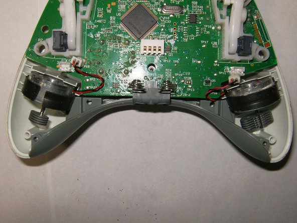
    • Here is a view of the inside of the controller. Note the vibration motors having different counter weights.

    • Remove the connector from the left motor (controller is positioned upside down, left controller will be shown right etc.)

  4. この手順は未翻訳です。 翻訳を手伝う。

    : 手順 4、 3の画像 1 : 手順 4、 3の画像 2 : 手順 4、 3の画像 3
    • Remove the connector from the right motor

    • Both motors are disconnected. Notice position of the motors inside the case for re-assembly.

    • Remove logic board

  5. この手順は未翻訳です。 翻訳を手伝う。

    : 手順 5、 3の画像 1 : 手順 5、 3の画像 2 : 手順 5、 3の画像 3
    • Notice placement of rubber membranes on the front case for reassembly.

    • To remove the covers of the analogs sticks, simply pull them from the mounting pegs.

    • View of the left analog stick to be removed.

  6. この手順は未翻訳です。 翻訳を手伝う。

    : 手順 6、 3の画像 1 : 手順 6、 3の画像 2 : 手順 6、 3の画像 3
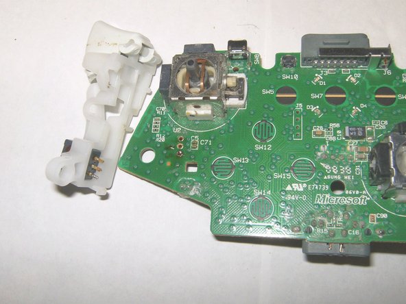
    • To remove the left analog stick, the left trigger button will have to be removed first. Desolder the three solder points. Use desoldering wick and some flux to remove the solder.

    • Left trigger points unsoldered.

    • There are 2 snaps holding the left trigger piece in place, remove those. It may take a bit of force, but simply push the snap over and down.

  7. この手順は未翻訳です。 翻訳を手伝う。

    : 手順 7、 3の画像 1 : 手順 7、 3の画像 2 : 手順 7、 3の画像 3
    • When removing the left trigger, make sure that the points are unsolderd properly, gently pull the trigger downward.

    • Left trigger removed.

    • With the left trigger removed, simply turn the logic board over and find the 14 solder connections

  8. この手順は未翻訳です。 翻訳を手伝う。

    : 手順 8、 3の画像 1 : 手順 8、 3の画像 2 : 手順 8、 3の画像 3
    • Use a desoldering wick and some flux to remove the solder.

    • Ensure that no other components get either desoldered or otherwise heat damaged.

    • Here, all points have been desoldered.

  9. この手順は未翻訳です。 翻訳を手伝う。

    : 手順 9、 3の画像 1 : 手順 9、 3の画像 2 : 手順 9、 3の画像 3
    • Pull off the 3D analog stick gently to ensure that all solder connections are unsoldered.

    • Remove the analog stick

    • Put the new 3D analog stick in place. Make sure that it is seated flush against the board.

  10. この手順は未翻訳です。 翻訳を手伝う。

    : 手順 10、 3の画像 1 : 手順 10、 3の画像 2 : 手順 10、 3の画像 3
    • Apply some flux to the solder points and the leg of the analog stick.

    • Solder the connections in place.

    • All points soldered back in place. The liquid black debris is flux. This can be removed by cleaning the board with some isopropyl alcohol after the soldering.

  11. この手順は未翻訳です。 翻訳を手伝う。

    : 手順 11、 1の画像 1
    • Here is the board with the new sticks and the left trigger button resoldered.

ゴール

43 の人々がこのガイドを完成させました。

作成者

3人の作成者と共同で作成されました。

oldturkey03

メンバー登録日: 09/29/10

783,763 ポイント

119のガイドは作成済み

チーム

Global Fixers Global Fixers人のメンバー

Community

33 メンバー

551のガイドは作成済み

14 件のコメント

My controller left stick is physically okew..but in gaming it is moving on downwards...

How can I fix this,I don't knew to do this repairing!:(

Mohamed Irfan - 返信

Nice work, excellenté!

sadiqusman23 - 返信

I would like to note, you can unscrew the security screws with a 00 Flat head screwdriver. I just did it now and got all the screws out. Just gotta find the sweet spot, but it works.

gickygouse19 - 返信

Where do you purchase the actual 2-axis module that get resoldered to the board?

ivymaccurtin - 返信

muy buen tutorial, ¿¿¿no te sabras los valores de los condensadores c5 y c71??? es que tube un incidente y los arranque los dos.

un saludo

David Martin - 返信

コメントを追加

統計データ:

過去 24時間: 14

過去 7 日: 89

過去 30 日: 358

今までの合計 106,042