メインコンテンツにスキップ
リペアコミュニティに参加 - アカウントの作成

Top Cover Removal

必要な工具と部品

    1. Top Cover Removal, Remove film door: 手順 1、 1の画像 1
      • Push down the latch to release the film door.

      FixBotに聞いてみる
      コメントを追加

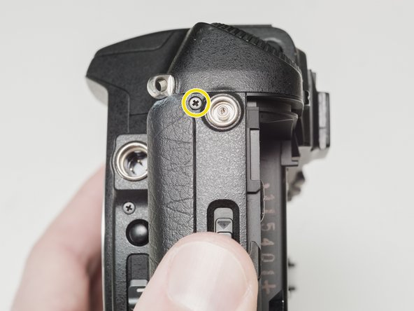
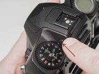
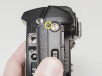
    2. Top Cover Removal, Remove top cover screws: 手順 2、 3の画像 1 Top Cover Removal, Remove top cover screws: 手順 2、 3の画像 2 Top Cover Removal, Remove top cover screws: 手順 2、 3の画像 3
      • Remove two 7.5 mm #00 screws.

      • Remove one 9.0 mm #00 screw.

      • Remove one 13.5 mm #00 screw from inside the battery compartment.

      FixBotに聞いてみる
      コメントを追加

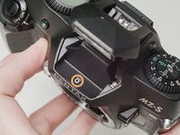
    3. Top Cover Removal, Remove top cover screws: 手順 3、 3の画像 1 Top Cover Removal, Remove top cover screws: 手順 3、 3の画像 2 Top Cover Removal, Remove top cover screws: 手順 3、 3の画像 3
      • Push the button to pop up the flash.

      • Remove one 3.5 mm #00 screw.

      • Remove one 5.5 mm #00 screw.

      FixBotに聞いてみる

      コメントを追加

    4. Top Cover Removal, Lift top cover: 手順 4、 1の画像 1
      • Carefully lift the top cover away from the body to access wired connections.

      • The top cover is still connected in several locations.

      FixBotに聞いてみる

      コメントを追加

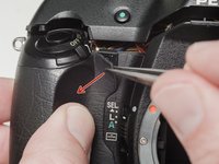
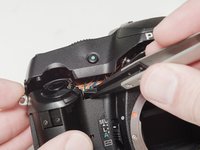
    5. Top Cover Removal, Access flash connections: 手順 5、 2の画像 1 Top Cover Removal, Access flash connections: 手順 5、 2の画像 2
      • Peel back the corner of the rubber grip.

      • Remove the small plastic cover.

      • Be careful not to short the wires before the flash capacitors have been properly discharged.

      FixBotに聞いてみる

      コメントを追加

    6. Top Cover Removal, Discharge flash capacitors: 手順 6、 1の画像 1
      • Use a 1kΩ-10kΩ high power resistor to discharge the capacitor. Place the resistor between the blue wire, exposed in the previous step, and ground.

      • The flash capacitors store energy at a very high voltage. Failing to discharge the capacitors properly could result in personal injury and/or damage to the camera.

      FixBotに聞いてみる

      コメントを追加

    7. Top Cover Removal, Disconnect right flex cable: 手順 7、 1の画像 1
      • Carefully lift the sides of the white latch.

      • Hold the flex PCB on the camera body in place as you lift to prevent damaging the flex.

      FixBotに聞いてみる

      コメントを追加

    8. Top Cover Removal, Disconnect left flex cable: 手順 8、 1の画像 1
      • Desolder the red wire.

      • Carefully lift the sides of the white latch.

      • Hold the flex PCB on the camera body in place as you lift to prevent damaging the flex.

      FixBotに聞いてみる

      コメントを追加

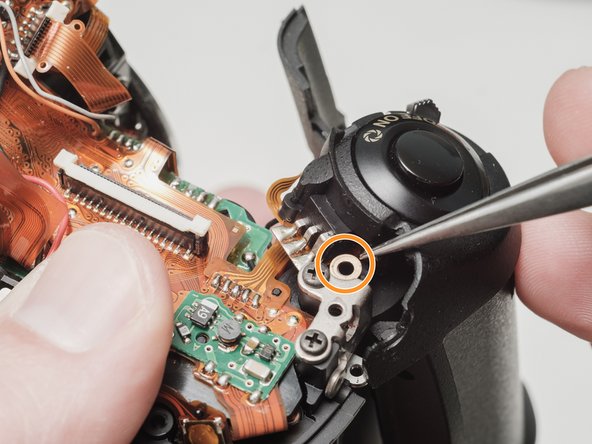
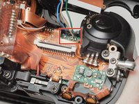
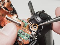
    9. Top Cover Removal, Desolder flash connections: 手順 9、 2の画像 1 Top Cover Removal, Desolder flash connections: 手順 9、 2の画像 2
      • Desolder blue, black, brown and green wires.

      • Remove the loose shim washer if present.

      FixBotに聞いてみる

      コメントを追加

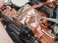
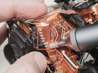
    10. Top Cover Removal, Desolder the flash flex cable: 手順 10、 2の画像 1 Top Cover Removal, Desolder the flash flex cable: 手順 10、 2の画像 2
      • Remove the piece of cellophane tape covering the flex connections.

      • Desolder flex connetions.

      FixBotに聞いてみる

      コメントを追加

終わりに

To reassemble your device, follow these instructions in reverse order.

キャンセル: このガイドを終了できませんでした。

作成者

1人の作成者と共同作成されました。

Sam Gustafson

メンバー登録日: 09/01/22

14,454 ポイント

78のガイドは作成済み

0件のガイドコメント

コメントを追加

統計データ:

過去 24時間: 0

過去 7 日: 5

過去 30 日: 31

今までの合計 560