はじめに
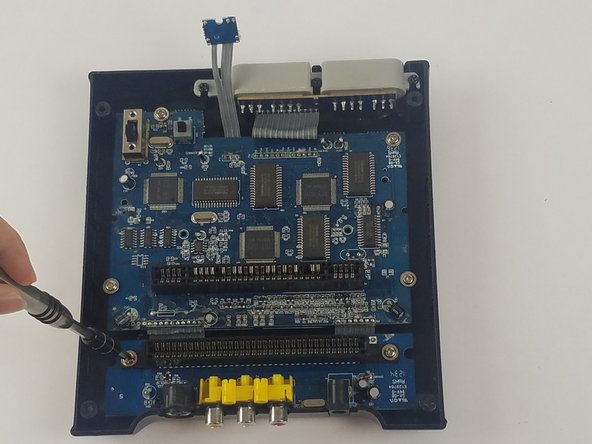
回路基板はコンソールの機能に不可欠なパーツです。プラスドライバー#0およびプラスドライバー#2を使用して交換します。
必要な工具と部品
-
-
-
-
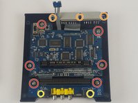
回路基板およびポートを固定している11本のネジを取り外します。
-
回路基板を固定している11 mmのプラスネジ(#2)6本。
-
コントローラーポートを固定している12 mmのプラスネジ(#2)3本。
-
背面ポートを固定している7 mmのプラスネジ(#2)2本
-
-
-
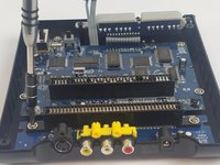
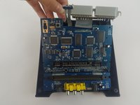
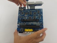
AVポートまたはコントローラーポートのいずれかを持ち、回路基板を慎重に持ち上げます。または、回路基板の端を持つこともできます。
-
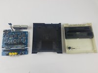
回路基板をボトムケースから完全に取り出してください。
-


デバイスを再組み立てするには、これらのインストラクションを逆の順番に従って作業を進めてください。
以下の翻訳者の皆さんにお礼を申し上げます:
100%

Translation Botさんは世界中で修理する私たちを助けてくれています! あなたも貢献してみませんか?
翻訳を始める ›
チーム

USF Tampa, Team S4-G4, Eyestone Fall 2017 USF Tampa, Team S4-G4, Eyestone Fall 2017人のメンバー
USFT-EYESTONE-F17S4G4
3 メンバー
55のガイドは作成済み
1件のガイドコメント
I hope you show the second part were you replace the 72pin connector. Please include part source.
The 72 pin connector grabs too tightly on the cart.
Thanks.