メインコンテンツにスキップ

このバージョンは誤った内容を含んでいる可能性があります。最新の承認済みスナップショットに切り替えてください。

必要な工具と部品

  1. この手順は未翻訳です。 翻訳を手伝う。

    : 手順 1、 3の画像 1 : 手順 1、 3の画像 2 : 手順 1、 3の画像 3
    • Here is the Amp in all its miniature glory. total size is 91/2 inches X 9 5/8inches and 6 inches deep. All controls are in the front panel.

    • Remove the 4 Phillips head screws from the back panel.

    • Here are the 4 #6x1" screws

  2. この手順は未翻訳です。 翻訳を手伝う。

    : 手順 2、 3の画像 1 : 手順 2、 3の画像 2 : 手順 2、 3の画像 3
    • Remove the back panel. Use a small screwdriver, or other instrument to free it from its recess.

    • Work your way all around, since the back is a bit snug in the recess.

  3. この手順は未翻訳です。 翻訳を手伝う。

    : 手順 3、 3の画像 1 : 手順 3、 3の画像 2 : 手順 3、 3の画像 3
    • Once the panel is freed from the recess, fold it down and remove from amp.

    • Something does not look quite right :-)

    • the transformer should be mounted to the PCB, not laying inside the box.

  4. この手順は未翻訳です。 翻訳を手伝う。

    : 手順 4、 3の画像 1 : 手順 4、 3の画像 2 : 手順 4、 3の画像 3
    • Trying to find a mount for it.

    • Closer view of the control panel PCB.

    • Mount for the transformer

    • Unoccupied connector

    • Fuse

    • Before anything else, check the fuse for continuity. this one has failed.

  5. この手順は未翻訳です。 翻訳を手伝う。

    : 手順 5、 3の画像 1 : 手順 5、 3の画像 2 : 手順 5、 3の画像 3
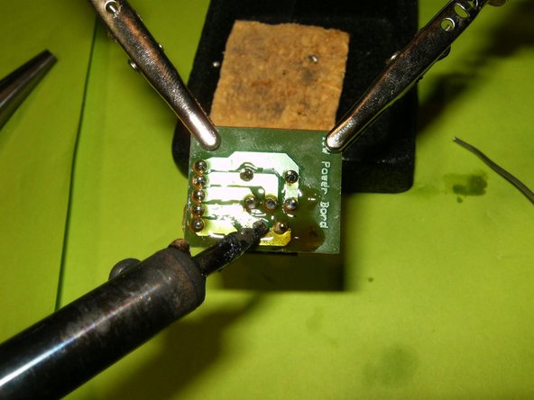
    • Replace the fuse. Insert transformer power cable to PCB.

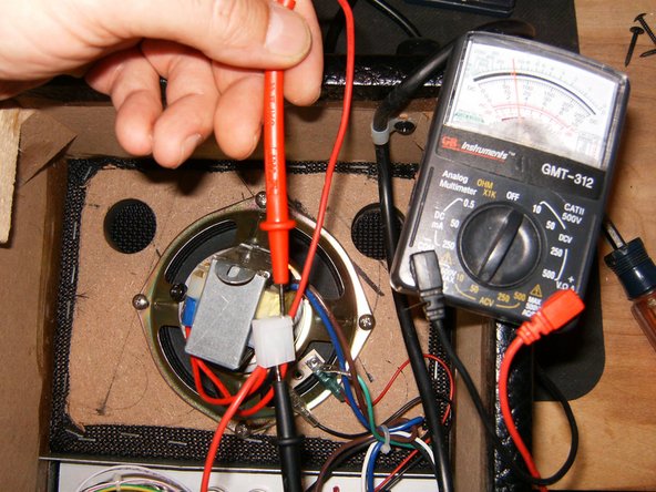
    • Since the Amp did not turn on, check the power out on the transformer. It does show 12V DC. Reconnect it and turn the Amp face forward.

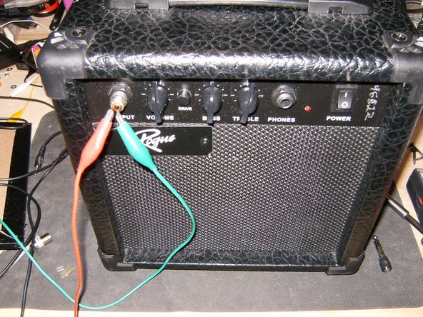
    • The Amp uses a 6.3mm input and output jack. Apply a sound source to the input. Still no sound from the Amp, it is time to check a bit deeper.

  6. この手順は未翻訳です。 翻訳を手伝う。

    : 手順 6、 3の画像 1 : 手順 6、 3の画像 2 : 手順 6、 3の画像 3
    • Remove the two Philips head screws from the carrying handle.

    • Those are 3mm x40mm

    • Remove the Philips screw on the right side of the Amp

  7. この手順は未翻訳です。 翻訳を手伝う。

    : 手順 7、 3の画像 1 : 手順 7、 3の画像 2 : 手順 7、 3の画像 3
    • Remove the Philips head screw on the left side of the Amp.

    • Unplug the speaker wires.

    • Remove the Philips head screw that holds the power cable bracket.

  8. この手順は未翻訳です。 翻訳を手伝う。

    : 手順 8、 3の画像 1 : 手順 8、 3の画像 2 : 手順 8、 3の画像 3
    • Remove the front panel and the attached speaker.

    • Simply lift it at an angle out of the back of the Amp.

    • The control panel and the attached PCB can now be removed.

  9. この手順は未翻訳です。 翻訳を手伝う。

    : 手順 9、 3の画像 1 : 手順 9、 3の画像 2 : 手順 9、 3の画像 3
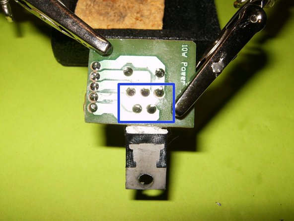
    • Another odd looking piece is the location of the power Amp IC.

    • The smudge marks of the thermal past revealed that the board was loose and the the IC did not make contact with the heatsink

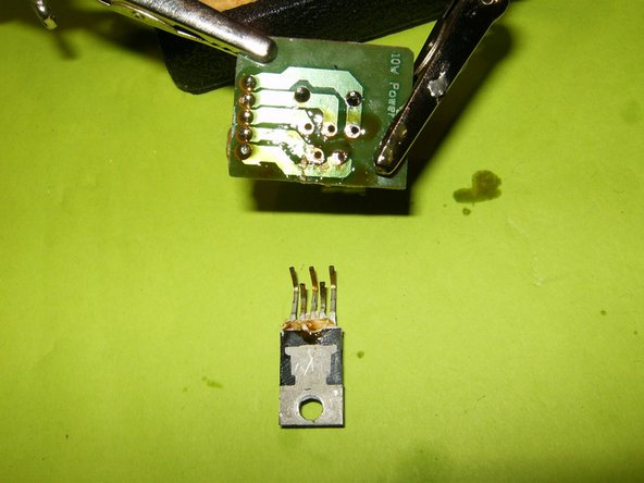
    • The thread in the heatsink was partially stripped. Use a small jewelers screwdriver to wedge under the screw,while using a #2 Philips screwdriver to remove it.

  10. この手順は未翻訳です。 翻訳を手伝う。

    : 手順 10、 3の画像 1 : 手順 10、 3の画像 2 : 手順 10、 3の画像 3
    • Remove the connector from the PCB.

    • Remove the IC PCB from the panel. The IC definitely shows some damage, most likely from overheating.

    • Here is a close up of the damaged IC. It is a TDA2030A 18 W hi-fi amplier / 35 W audio driver

  11. この手順は未翻訳です。 翻訳を手伝う。

    : 手順 11、 3の画像 1 : 手順 11、 3の画像 2 : 手順 11、 3の画像 3
    • These are the tools needed to replace the IC. 15W Soldering iron, flux and desoldering wick.

    • These are the five contacts that need to be desoldered. Apply some flux on the wick and heat up the solder with the soldering iron.

    • Remove the damaged IC

  12. この手順は未翻訳です。 翻訳を手伝う。

    : 手順 12、 3の画像 1 : 手順 12、 3の画像 2 : 手順 12、 3の画像 3
    • Insert wisdom here.

  13. この手順は未翻訳です。 翻訳を手伝う。

    : 手順 13、 3の画像 1 : 手順 13、 3の画像 2 : 手順 13、 3の画像 3
    • Here is the replacement IC.

    • Place the IC properly on the PCB

    • Solder it in place.

  14. この手順は未翻訳です。 翻訳を手伝う。

    : 手順 14、 2の画像 1 : 手順 14、 2の画像 2
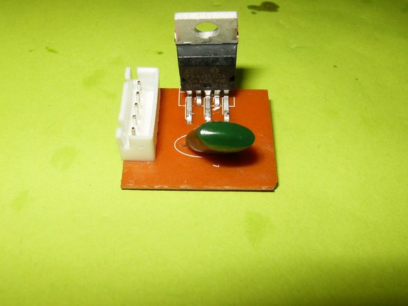
    • Reapply a thin coat of thermal paste to the back of the IC. Use a self tapping screw to attach it to the heatsink.

    • Now is also a good time to properly mount the transformer. I used some M3x15mm machine screws.

    • With those repairs made, all that is left is to reassemble the AMP. In my case, this Amp worked after replacing the TDA2030A

ゴール

14 の人々がこのガイドを完成させました。

作成者

2人の作成者と共同で作成されました。

oldturkey03

メンバー登録日: 09/29/10

783,943 ポイント

119のガイドは作成済み

チーム

Global Fixers Global Fixers人のメンバー

Community

33 メンバー

555のガイドは作成済み

コメント 1 件

Good Job! Very detailed, narratives good, and photos were excellent for a learning tool. Matt of Martins TV Repair.

Matt Martin - 返信

コメントを追加

統計データ:

過去 24時間: 1

過去 7 日: 12

過去 30 日: 44

今までの合計 21,279