メインコンテンツにスキップ

Protocol TerraCopter EVO Controller Motherboard Replacement

必要な工具と部品

  1. Protocol TerraCopter EVO Controller Motherboard Replacement, Controller's battery: 手順 1、 2の画像 1 Protocol TerraCopter EVO Controller Motherboard Replacement, Controller's battery: 手順 1、 2の画像 2
    • Using a Phillips #0 screwdriver, remove the screw connecting the battery cover to the controller.

    • Remove the battery cover from the controller.

  2. Protocol TerraCopter EVO Controller Motherboard Replacement: 手順 2、 1の画像 1
    • Remove all of four of the AA batteries from the controller.

  3. 注意: 手順 3-4 は、作業進行中としてマークされている ガイド から引用されています。

    Protocol TerraCopter EVO Controller Motherboard Replacement, Protocol TerraCopter EVO Controller Opening: 手順 3、 1の画像 1
    • Note: the four Phillips screws on the rear panel are a millimeter longer than the two screws near the antenna and the two screws on the handle.

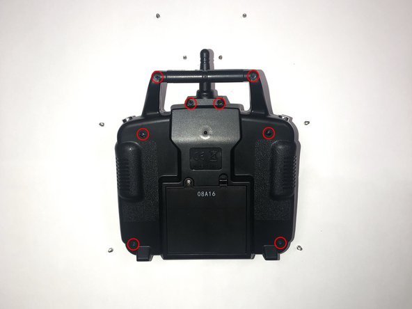
    • Orientate the controller to where the battery compartment is facing upwards.

    • Remove the four 5mm and four 4mm Phillips #1 screws from the case.

  4. Protocol TerraCopter EVO Controller Motherboard Replacement: 手順 4、 1の画像 1
    • Since the battery wires are still attached, carefully move the rear panel down to expose the motherboard.

  5. Protocol TerraCopter EVO Controller Motherboard Replacement, Controller Motherboard: 手順 5、 1の画像 1
    • Remove the eight 5mm Phillips #1 screws from the motherboard.

  6. Protocol TerraCopter EVO Controller Motherboard Replacement: 手順 6、 1の画像 1
    • Locate the set of four green wires and one black wire attached to the motherboard.

    • Remove the male, white connector by pressing up on the two tabs on the female connector. Then, pull the connector away from the female connector on the motherboard

  7. Protocol TerraCopter EVO Controller Motherboard Replacement: 手順 7、 1の画像 1
    • Locate the single pin holding the negative and positive wires to the motherboard. Each lead should have one pin holding each wire to the green side of the motherboard.

    • Using a soldering iron, melt the existing solder point for the red lead (positive line).

    • Using a soldering iron, melt the existing solder point for the black lead (negative line).

    • Pull the red and black leads through their respective holes, out of the motherboard.

    • Check out our How to Solder and Desolder Connections guide if you are unfamiliar with soldering practices.

終わりに

To reassemble your device, follow these instructions in reverse order.

ある他の人がこのガイドを完成しました。

作成者

2人の作成者と共同で作成されました。

Jonathan Earls

メンバー登録日: 10/03/19

127 ポイント

1ガイドが承認済み

0 件のコメント

コメントを追加

統計データ:

過去 24時間: 0

過去 7 日: 0

過去 30 日: 2

今までの合計 108