このバージョンは誤った内容を含んでいる可能性があります。最新の承認済みスナップショットに切り替えてください。
はじめに
このガイドを参照して、損傷したフロントベゼルを交換しましょう。
必要な工具と部品
-
この手順は未翻訳です。 翻訳を手伝う。
-
On the keyboard, remove the F1, F2, F11, and F12 keys.
-
This is scary - take a deep breath before continuing. Place your index finger under the upper left corner of the key and lift up until you hear a click. Then, transfer your finger to the left edge of the key and lift up to pull the key off.
-
You're freeing the two tabs on the left of the key from the two small holes in the plastic scissors mechanism.
-
-
この手順は未翻訳です。 翻訳を手伝う。
-
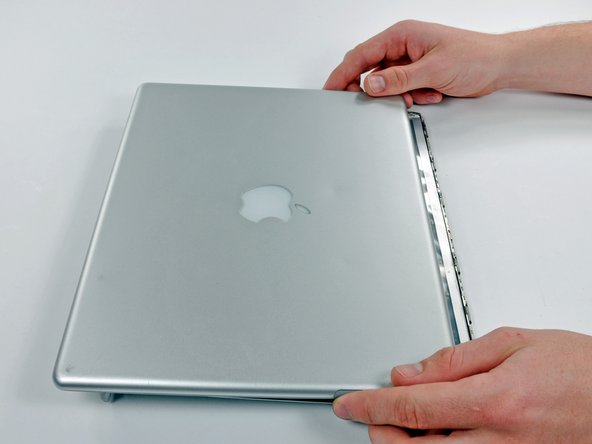
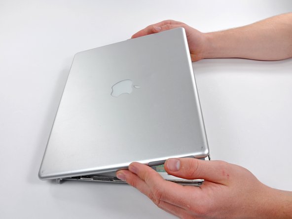
Turn the computer over and open it up.
-
Remove the following 14 screws:
-
Six 2.5 mm Phillips on either side of the keyboard area.
-
Five 4.5 mm Phillips on the left half of the keyboard area.
-
One 7 mm hex in the upper left corner of the upper case (a T6 Torx driver will do the job nicely).
-
One 15 mm Phillips in the upper middle of the keyboard area.
-
One 16.5 mm hex in the upper right of the upper case (again, a T6 Torx driver will work well).
-
-
この手順は未翻訳です。 翻訳を手伝う。
-
Peel up the two pieces of foil tape on the left side of the keyboard area.
-
Carefully disconnect the microphone and power cables from the logic board. Using your fingernails or a dental pick, carefully pry the connectors from their sockets. Make sure you're pulling only on the connector and not on the socket.
-
-
-
この手順は未翻訳です。 翻訳を手伝う。
-
Peeling up yellow tape as necessary, remove the following 8 screws:
-
One 4.5 mm Phillips on the right side of the heat sink.
-
Three 6 mm Phillips near the display.
-
Two large 7.5 mm Phillips with springs (don't forget to remove the springs). If the springs are not releasing, needle nose pliers can help get this done.
-
Two 13 mm screws from the left side of the heat sink and the right side of the fan.
-
-
この手順は未翻訳です。 翻訳を手伝う。
-
Remove the following five screws:
-
One 3 mm Phillips near the screen latch (mind the big magnet on the screen latch).
-
Two 3.5 mm Phillips attaching the EMI fingers to the metal framework.
-
One 10 mm Phillips near the optical drive.
-
One 14 mm long 4 mm standoff in the upper left corner. You can remove this standoff either with a 4 mm nut driver or needlenose pliers.
-
Lift the EMI fingers above the battery connector away from the metal framework.
-
-
この手順は未翻訳です。 翻訳を手伝う。
-
Remove the following 5 screws:
-
One 4.5 mm Phillips in the bottom left corner of the logic board.
-
Two 6 mm Phillips to the left of the display hinge.
-
One 10 mm Phillips to the upper left of the fan area.
-
One 13 mm Phillips to the right of the headphone jack on the metal framework.
-
-
この手順は未翻訳です。 翻訳を手伝う。
-
The tip of my power supply plug broke off inside the power receptacle.
-
Once the DC-in board has been removed.
-
Peal back the metal RFI shield.
-
At the back of the power receptacle - gently pull the top of the center tab out away from the receptacle body. Forming a gap.
-
From the front of the receptacle - use a screwdriver to push the broken tip out the gap.
-
Push the center tab back in place.
-
Replace the RFI shield.
-
-
この手順は未翻訳です。 翻訳を手伝う。
-
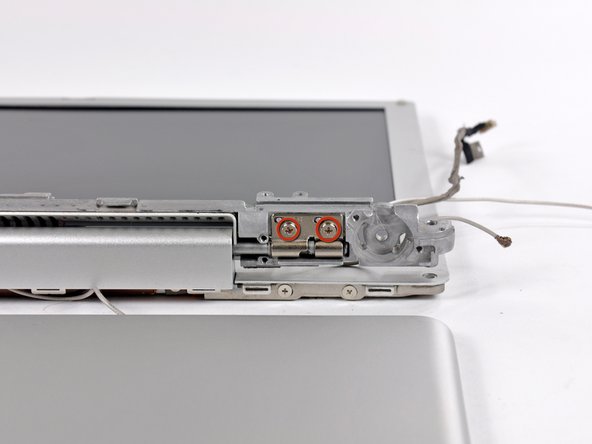
Remove the two Phillips screws from the upper right corner of the computer.
-
Remove the newly-liberated small metal bracket.
-
-
この手順は未翻訳です。 翻訳を手伝う。
-
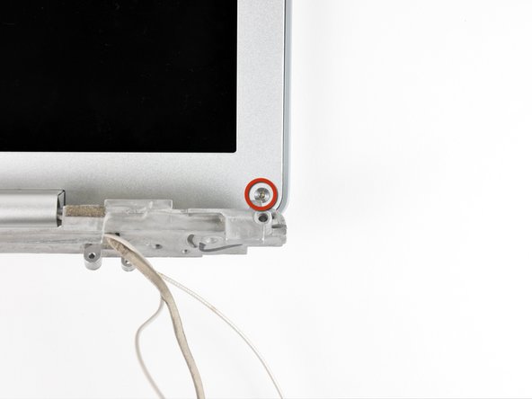
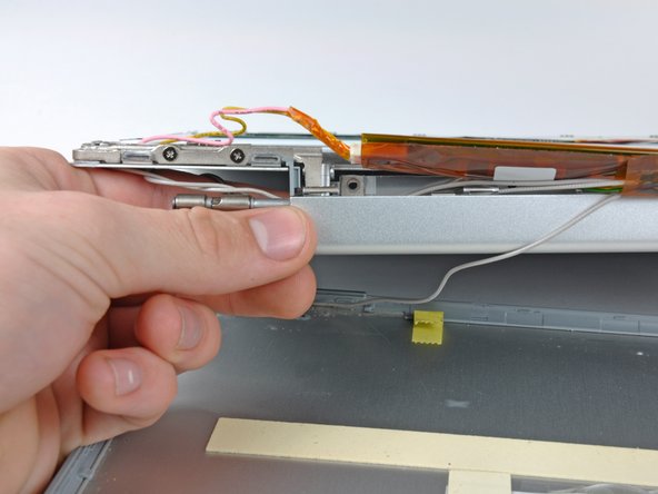
Remove the two T6 Torx screws in the lower left and lower right corners of the display securing the rear bezel to the display assembly.
-
-
この手順は未翻訳です。 翻訳を手伝う。
-
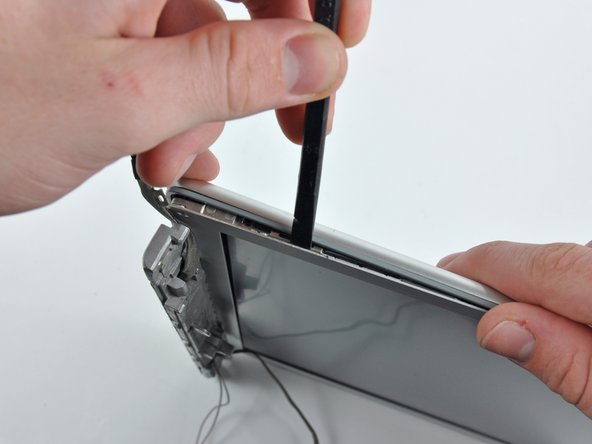
Insert the spudger between the left edge of the front display bezel and the plastic strip attached to the rear bezel, with the edge of the tool angled toward the LCD.
-
Rotate the tool away from the LCD to pop the rear bezel off the tabs on the front display bezel.
-
Work along the left edge of the display until the rear bezel is evenly separated from the front bezel.
-
-
この手順は未翻訳です。 翻訳を手伝う。
-
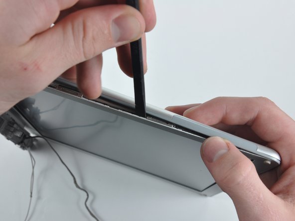
Insert a spudger between the right edge of the front display bezel and the plastic strip attached to the rear bezel, with the edge of the tool angled toward the LCD.
-
Rotate the tool away from the LCD to pop the rear bezel off the tabs on the front display bezel.
-
Work along the right edge of the display until the rear bezel is evenly separated from the front bezel.
-
-
この手順は未翻訳です。 翻訳を手伝う。
-
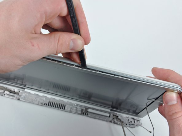
Insert a spudger between the top edge of the front display bezel and the plastic strip attached to the rear bezel, with the edge of the tool angled toward the LCD.
-
Rotate the tool away from the LCD to pop the rear bezel off the tabs on the front display bezel.
-
Work along the top edge of the display until the rear bezel is evenly separated from the front bezel.
-
-
この手順は未翻訳です。 翻訳を手伝う。
-
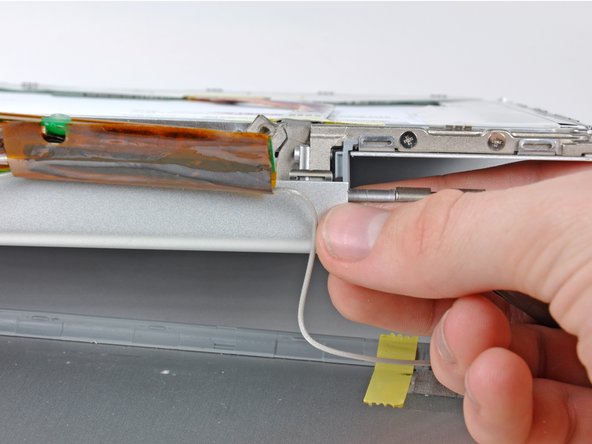
Flip the device over and remove the two 4.5 mm Phillips screws on each side of the metal bracket (four screws in total).
-
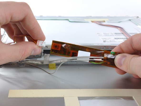
Thread the display inverter, antenna, and display data cables through the bracket and remove the metal bracket.
-


デバイスを再度組み立てるには、この説明書の逆の順番で組み立ててください。
デバイスを再度組み立てるには、この説明書の逆の順番で組み立ててください。
2 の人々がこのガイドを完成させました。
