メインコンテンツにスキップ
リペアコミュニティに参加 - アカウントの作成

Pangolin PC Assembly

必要な工具と部品

  1. Pangolin PC Assembly, Print Your Parts!: 手順 1、 1の画像 1
    • Before beginning, you must have all the required parts already printed.

    • You may not be able to assemble your PC properly without printing all the parts provided.

    • Actually, you won’t be able to do anything if you don’t have your parts printed before you begin.

    FixBotに聞いてみる

    コメントを追加

  2. Pangolin PC Assembly, Bottom Plate & Display Arm: 手順 2、 2の画像 1 Pangolin PC Assembly, Bottom Plate & Display Arm: 手順 2、 2の画像 2
    • For steps 2-4, you will use the following:

    • 1x pangolinpc_base.

    • 1x pangolinpc_display_arm.

    • 4x M5 screws.

    FixBotに聞いてみる

    コメントを追加

  3. Pangolin PC Assembly, Bottom Plate & Display Arm (cont.): 手順 3、 3の画像 1 Pangolin PC Assembly, Bottom Plate & Display Arm (cont.): 手順 3、 3の画像 2 Pangolin PC Assembly, Bottom Plate & Display Arm (cont.): 手順 3、 3の画像 3
    • Grab the pangolinpc_display_arm and place it on top of the pangolinpc_base and flip over these pieces.

    • Make sure that the holes outlined match up so you may screw them together.

    • The reason that there isn’t a fourth hole in the third photo is because this is a pre-release prototype. Versions 0.3-alpha and later should have the fourth hole.

    FixBotに聞いてみる

    コメントを追加

  4. Pangolin PC Assembly, Bottom Plate & Display Arm (cont.): 手順 4、 3の画像 1 Pangolin PC Assembly, Bottom Plate & Display Arm (cont.): 手順 4、 3の画像 2 Pangolin PC Assembly, Bottom Plate & Display Arm (cont.): 手順 4、 3の画像 3
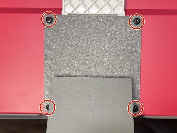
    • Screw in 4x M5 screws into the four holes.

    FixBotに聞いてみる

    コメントを追加

  5. Pangolin PC Assembly, Installing the SBC: 手順 5、 3の画像 1 Pangolin PC Assembly, Installing the SBC: 手順 5、 3の画像 2 Pangolin PC Assembly, Installing the SBC: 手順 5、 3の画像 3
    • For step 5, you will need the following:

    • The assembly from steps 2-4, which will be referred to now on as the "pangolinpc_base assembly."

    • The Single Board Computer (SBC), which in this case is a Raspberry Pi 5.

    • If you are going to install any HATs or accessories to the SBC, such as an PCIe HAT or the Active Cooler, install them now before proceeding.

    • You will place the SBC in the special slide-in area.

    • Line up the edges of the SBC with the notches in the slide-in area. Then slide the SBC down towards the rear of the pangolinpc_base.

    FixBotに聞いてみる

    コメントを追加

  6. Pangolin PC Assembly, Installing the Webcam Cable: 手順 6、 3の画像 1 Pangolin PC Assembly, Installing the Webcam Cable: 手順 6、 3の画像 2 Pangolin PC Assembly, Installing the Webcam Cable: 手順 6、 3の画像 3
    • For steps 6-8, you will need the following:

    • 1x Webcam cable.

    • The pangolinpc_base assembly.

    • Find the display/camera connectors on the right side of the SBC.

    • You will be plugging the cable into the connector nearest the Ethernet port on the SBC. This port is also labeled "CAM/DISP 0."

    • Pull up the brown clip of the connector.

    FixBotに聞いてみる

    コメントを追加

  7. Pangolin PC Assembly, Installing the Webcam Cable (cont.): 手順 7、 2の画像 1 Pangolin PC Assembly, Installing the Webcam Cable (cont.): 手順 7、 2の画像 2
    • Make sure you insert the smaller side of the cable into the SBC. The other side won't fit!

    • Insert the cable into the port. Don't force it! They are called "ZIF" (Zero Insertion Force) for a reason!

    • Insert the side of the cable with the gold contacts facing away from the Ethernet port.

    • Press down the brown clip to secure the cable.

    FixBotに聞いてみる

    コメントを追加

  8. Pangolin PC Assembly, Installing the Webcam Cable (cont.): 手順 8、 3の画像 1 Pangolin PC Assembly, Installing the Webcam Cable (cont.): 手順 8、 3の画像 2 Pangolin PC Assembly, Installing the Webcam Cable (cont.): 手順 8、 3の画像 3
    • Insert the fat end of the Webcam cable into the pangolinpc_display_arm and thread it through.

    • Pull the cable out through the top of the pangolinpc_display_arm.

    • There should be little slack inside the assembly, but don't pull too tight!

    FixBotに聞いてみる

    コメントを追加

  9. Pangolin PC Assembly, Installing the HDMI Cable: 手順 9、 3の画像 1 Pangolin PC Assembly, Installing the HDMI Cable: 手順 9、 3の画像 2 Pangolin PC Assembly, Installing the HDMI Cable: 手順 9、 3の画像 3
    • For steps 9-10, you will use the following:

    • 1x Micro-HDMI to HDMI cable.

    • The pangolinpc_base assembly.

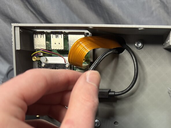
    • Insert the Micro end into the top of the pangolinpc_display_arm, and thread it through so it comes out inside the assembly.

    FixBotに聞いてみる

    コメントを追加

  10. Pangolin PC Assembly, Installing the HDMI Cable (cont.): 手順 10、 2の画像 1 Pangolin PC Assembly, Installing the HDMI Cable (cont.): 手順 10、 2の画像 2
    • Insert the cable into the port nearest the USB-C port, marked HDMI0.

    FixBotに聞いてみる

    コメントを追加

  11. Pangolin PC Assembly, Installing the USB-C Cable: 手順 11、 2の画像 1 Pangolin PC Assembly, Installing the USB-C Cable: 手順 11、 2の画像 2
    • For steps 11-12, you will use the following:

    • 1x USB-C Power Cable.

    • The pangolinpc_base assembly.

    • I would highly recommend winding up the excess cable, making nice, neat loop near the power supply end of the cable.

    FixBotに聞いてみる

    コメントを追加

  12. Pangolin PC Assembly, Installing the USB-C Cable (cont.): 手順 12、 2の画像 1 Pangolin PC Assembly, Installing the USB-C Cable (cont.): 手順 12、 2の画像 2
    • Pull the USB-C cable through the pangolinpc_display_arm.

    FixBotに聞いてみる

    コメントを追加

  13. Pangolin PC Assembly, Installing the Power Strip: 手順 13、 3の画像 1 Pangolin PC Assembly, Installing the Power Strip: 手順 13、 3の画像 2 Pangolin PC Assembly, Installing the Power Strip: 手順 13、 3の画像 3
    • For steps 13-14, you will use the following:

    • 1x Power Strip.

    • The pangolinpc_base assembly.

    • Insert the power strip into the pangolinpc_base, where there is a large hole on the right side.

    • Push the power strip down into the pangolinpc_base until it stops.

    FixBotに聞いてみる

    コメントを追加

  14. Pangolin PC Assembly, Installing the Power Strip (cont.): 手順 14、 2の画像 1 Pangolin PC Assembly, Installing the Power Strip (cont.): 手順 14、 2の画像 2
    • In the second photo, this is what your pangolinpc_base should look like inside.

    FixBotに聞いてみる

    コメントを追加

  15. Pangolin PC Assembly, Installing the Anker Power Supply: 手順 15、 3の画像 1 Pangolin PC Assembly, Installing the Anker Power Supply: 手順 15、 3の画像 2 Pangolin PC Assembly, Installing the Anker Power Supply: 手順 15、 3の画像 3
    • For steps 15-16, you will need the following:

    • 1x Anker Power Supply.

    • The pangolinpc_base assembly.

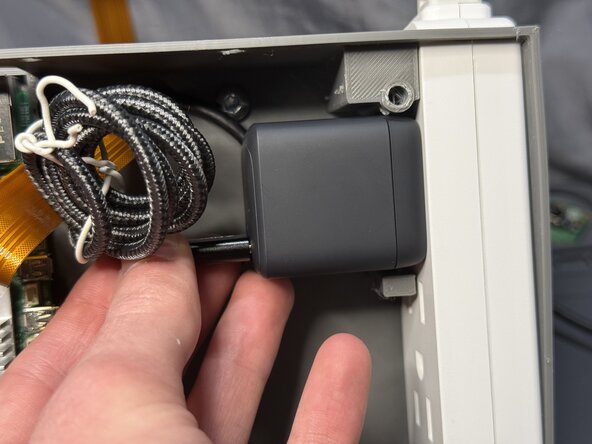
    • You will be plugging the power supply into the port closest to the rear of the assembly.

    • Plug the power supply into the port.

    • Make sure the USB-C port on the power supply is closest to the front of the assembly. (See next step to see proper orientation.)

    FixBotに聞いてみる

    コメントを追加

  16. Pangolin PC Assembly, Installing the Anker Power Supply (cont.): 手順 16、 3の画像 1 Pangolin PC Assembly, Installing the Anker Power Supply (cont.): 手順 16、 3の画像 2 Pangolin PC Assembly, Installing the Anker Power Supply (cont.): 手順 16、 3の画像 3
    • Just like in the last step, make sure the USB-C port is closest to the front of the assembly.

    • Plug the USB-C cable into the power supply.

    FixBotに聞いてみる

    コメントを追加

  17. Pangolin PC Assembly, Installing the RPi Power Supply: 手順 17、 3の画像 1 Pangolin PC Assembly, Installing the RPi Power Supply: 手順 17、 3の画像 2 Pangolin PC Assembly, Installing the RPi Power Supply: 手順 17、 3の画像 3
    • For steps 17-18, you will need the following:

    • 1x Raspberry Pi power supply.

    • The pangolinpc_base assembly.

    • It is highly recommended to wind up the excess wire with a twist tie.

    • Plug the power supply into the bottom port on the power strip.

    • Make sure the cord coming out of the power supply is coming out closest to the front of the assembly.

    FixBotに聞いてみる

    コメントを追加

  18. Pangolin PC Assembly, Installing the RPi Power Supply (cont.): 手順 18、 3の画像 1 Pangolin PC Assembly, Installing the RPi Power Supply (cont.): 手順 18、 3の画像 2 Pangolin PC Assembly, Installing the RPi Power Supply (cont.): 手順 18、 3の画像 3
    • You will plug the USB-C cable into the Raspberry Pi's power port.

    • Plug in the cable.

    FixBotに聞いてみる

    コメントを追加

  19. Pangolin PC Assembly, What It Should Look Like So Far: 手順 19、 1の画像 1
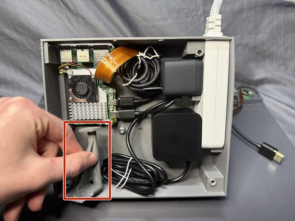
    • This is what your pangolinpc_base assembly should look like inside.

    FixBotに聞いてみる

    コメントを追加

  20. Pangolin PC Assembly, Assembling the Power Button Assembly: 手順 20、 1の画像 1
    • For step 20, you will need the following:

    • 1x pangolinpc_power_button.

    • 1x pangolinpc_power_button_assembly_arm.

    • Hot glue.

    • Apply a wave pattern of glue to the pangolinpc_power_button and attach it to pangolinpc_power_button_assembly_arm as shown in the photo.

    • Make sure that the top of the pangolinpc_power_button is flush with the bottom of the pangolinpc_power_button_assembly_arm.

    FixBotに聞いてみる

    コメントを追加

  21. Pangolin PC Assembly, Installing the Power Button Assembly: 手順 21、 3の画像 1 Pangolin PC Assembly, Installing the Power Button Assembly: 手順 21、 3の画像 2 Pangolin PC Assembly, Installing the Power Button Assembly: 手順 21、 3の画像 3
    • For step 21-22, you will need the following:

    • The pangolinpc_power_button_assembly_arm assembly.

    • The pangolinpc_base assembly.

    • Hot glue.

    • Install the pangolinpc_power_button_assembly_arm assembly so that the power button is flush where the hole is for the power button on the pangolinpc_base.

    FixBotに聞いてみる

    コメントを追加

  22. Pangolin PC Assembly, Installing the Power Button Assembly (cont.): 手順 22、 2の画像 1 Pangolin PC Assembly, Installing the Power Button Assembly (cont.): 手順 22、 2の画像 2
    • Apply hot glue to the areas shown with the red lines.

    FixBotに聞いてみる

    コメントを追加

  23. Pangolin PC Assembly, Assembling and Installing the Plate Feet and Bottom Plate: 手順 23、 3の画像 1 Pangolin PC Assembly, Assembling and Installing the Plate Feet and Bottom Plate: 手順 23、 3の画像 2 Pangolin PC Assembly, Assembling and Installing the Plate Feet and Bottom Plate: 手順 23、 3の画像 3
    • For step 23-24, you will need the following:

    • 2x pangolinpc_plate_legs.

    • 1x pangolinpc_base_bottom_plate.

    • Hot glue.

    • You will be gluing the pangolinpc_plate_legs to the rear of the pangolinpc_base_bottom_plate where there are indents.

    • Do not glue the pangolinpc_plate_legs to the side that has holes inside the indents.

    FixBotに聞いてみる

    コメントを追加

  24. Pangolin PC Assembly, Assembling and Installing the Plate Feet and Bottom Plate (cont.): 手順 24、 3の画像 1 Pangolin PC Assembly, Assembling and Installing the Plate Feet and Bottom Plate (cont.): 手順 24、 3の画像 2 Pangolin PC Assembly, Assembling and Installing the Plate Feet and Bottom Plate (cont.): 手順 24、 3の画像 3
    • Install the pangolinpc_base_bottom_plate assembly to the bottom of the pangolinpc_base assembly as shown.

    FixBotに聞いてみる

    コメントを追加

  25. Pangolin PC Assembly, Installing the Last Bottom Plate Screws: 手順 25、 2の画像 1 Pangolin PC Assembly, Installing the Last Bottom Plate Screws: 手順 25、 2の画像 2
    • For step 25, you will need the following:

    • 2x M5 screws.

    • Screw in the screws into the back holes on the pangolinpc_base assembly.

    FixBotに聞いてみる

    コメントを追加

  26. Pangolin PC Assembly, Assembling and Installing the Rear Plate Legs: 手順 26、 3の画像 1 Pangolin PC Assembly, Assembling and Installing the Rear Plate Legs: 手順 26、 3の画像 2 Pangolin PC Assembly, Assembling and Installing the Rear Plate Legs: 手順 26、 3の画像 3
    • For step 26-27, you will need the following:

    • 2x pangolinpc_plate_legs.

    • 2x M5 screws.

    • Hot glue.

    • Apply a thin bead of hot glue to the circumference of the screw head, as shown by the red circle.

    • Then place the screw into the pangolinpc_plate_legs so that the bottom of the screw head is flush with the top of the legs.

    FixBotに聞いてみる

    コメントを追加

  27. Pangolin PC Assembly, Assembling and Installing the Rear Plate Legs: 手順 27、 2の画像 1 Pangolin PC Assembly, Assembling and Installing the Rear Plate Legs: 手順 27、 2の画像 2
    • Install the M5 screw assemblies to the pangolinpc_base assembly.

    FixBotに聞いてみる

    コメントを追加

  28. Pangolin PC Assembly, Installing the VESA Mount: 手順 28、 1の画像 1
    • For steps 28-30, you will use the following:

    • The pangolinpc_vesa_mount

    • 4x M5 screws

    FixBotに聞いてみる

    コメントを追加

  29. Pangolin PC Assembly, Installing the VESA Mount (cont.): 手順 29、 3の画像 1 Pangolin PC Assembly, Installing the VESA Mount (cont.): 手順 29、 3の画像 2 Pangolin PC Assembly, Installing the VESA Mount (cont.): 手順 29、 3の画像 3
    • Thread the HDMI, USB-C, and Webcam cables through the middle square hole in the pangolinpc_vesa_mount.

    FixBotに聞いてみる

    コメントを追加

  30. Pangolin PC Assembly, Installing the VESA Mount (cont.): 手順 30、 3の画像 1 Pangolin PC Assembly, Installing the VESA Mount (cont.): 手順 30、 3の画像 2 Pangolin PC Assembly, Installing the VESA Mount (cont.): 手順 30、 3の画像 3
    • Screw the four M5 screws in the pangolinpc_vesa_mount, attaching it the pangolinpc_base assembly.

    FixBotに聞いてみる

    コメントを追加

  31. Pangolin PC Assembly, Installing the Display: 手順 31、 1の画像 1
    • For steps 31-35, you will need the following parts:

    • Raspberry Pi Display.

    • The pangolinpc_base assembly.

    • 4x M4 VESA screws.

    FixBotに聞いてみる

    コメントを追加

  32. Pangolin PC Assembly, Installing the Display (cont.): 手順 32、 2の画像 1 Pangolin PC Assembly, Installing the Display (cont.): 手順 32、 2の画像 2
    • Flip over the Display.

    • Flip over the white Display stand, making as flush with the back of the Display as possible.

    FixBotに聞いてみる

    コメントを追加

  33. Pangolin PC Assembly, Installing the Display (cont.): 手順 33、 3の画像 1 Pangolin PC Assembly, Installing the Display (cont.): 手順 33、 3の画像 2 Pangolin PC Assembly, Installing the Display (cont.): 手順 33、 3の画像 3
    • Take the pangolinpc_base assembly and have the power button pointing down, holding the Display arm above the Display's VESA mounting points.

    • Thread the Webcam cable under the white Display stand.

    • Thread it all the way so the end of the cable is sticking out the top end of the Display

    FixBotに聞いてみる

    コメントを追加

  34. Pangolin PC Assembly, Installing the Display (cont.): 手順 34、 3の画像 1 Pangolin PC Assembly, Installing the Display (cont.): 手順 34、 3の画像 2 Pangolin PC Assembly, Installing the Display (cont.): 手順 34、 3の画像 3
    • Plug the USB-C cable into the Display's USB-C port.

    • Plug the HDMI cable into the Display's HDMI port.

    • If you have any slack, just fold them in the well where the ports are.

    FixBotに聞いてみる

    コメントを追加

  35. Pangolin PC Assembly, Installing the Display (cont.): 手順 35、 3の画像 1 Pangolin PC Assembly, Installing the Display (cont.): 手順 35、 3の画像 2 Pangolin PC Assembly, Installing the Display (cont.): 手順 35、 3の画像 3
    • You will be screwing in 4x M4 VESA screws into these four holes on the pangolinpc_vesa_mount.

    • Make sure to support the pangolinpc_base to prevent any damage if the assembly is hanging down.

    FixBotに聞いてみる

    コメントを追加

  36. Pangolin PC Assembly, The Final Stretch!: 手順 36、 1の画像 1
    • You're almost done! 🫡👍

    • Take a moment to appreciate your work so far (or go get a coffee or a cookie).

    FixBotに聞いてみる

    コメントを追加

  37. Pangolin PC Assembly, Assembling and Installing the Webcam Assembly: 手順 37、 2の画像 1 Pangolin PC Assembly, Assembling and Installing the Webcam Assembly: 手順 37、 2の画像 2
    • For steps 37-43, you will use the following:

    • 1x pangolinpc_webcam_mount.

    • 1x pangolinpc_webcam_mount_plate.

    • 1x Raspberry Pi Camera Module.

    • 2x M5 screws.

    FixBotに聞いてみる

    コメントを追加

  38. Pangolin PC Assembly, Assembling and Installing the Webcam Assembly (cont.): 手順 38、 3の画像 1 Pangolin PC Assembly, Assembling and Installing the Webcam Assembly (cont.): 手順 38、 3の画像 2 Pangolin PC Assembly, Assembling and Installing the Webcam Assembly (cont.): 手順 38、 3の画像 3
    • Place the Camera Module onto the pangolinpc_webcam_mount_plate, matching up the four pins on the plate with the holes on the Camera Module.

    FixBotに聞いてみる

    コメントを追加

  39. Pangolin PC Assembly, Assembling and Installing the Webcam Assembly (cont.): 手順 39、 2の画像 1 Pangolin PC Assembly, Assembling and Installing the Webcam Assembly (cont.): 手順 39、 2の画像 2
    • Thread the Webcam cable through the slot near the top of the pangolinpc_webcam_mount.

    FixBotに聞いてみる

    コメントを追加

  40. Pangolin PC Assembly, Assembling and Installing the Webcam Assembly (cont.): 手順 40、 3の画像 1 Pangolin PC Assembly, Assembling and Installing the Webcam Assembly (cont.): 手順 40、 3の画像 2 Pangolin PC Assembly, Assembling and Installing the Webcam Assembly (cont.): 手順 40、 3の画像 3
    • Unscrew the top two M4 VESA screws holding the Display to the pangolinpc_vesa_mount.

    • Align the bottom two screw holes on the pangolinpc_webcam_mount.

    • Replace the two M4 VESA screws, attaching the pangolinpc_webcam_mount to the pangolinpc_vesa_mount and Display.

    FixBotに聞いてみる

    コメントを追加

  41. Pangolin PC Assembly, Assembling and Installing the Webcam Assembly (cont.): 手順 41、 1の画像 1
    • This is what the back of your Pangolin PC should look like after Step 40.

    FixBotに聞いてみる

    コメントを追加

  42. Pangolin PC Assembly, Assembling and Installing the Webcam Assembly (cont.): 手順 42、 2の画像 1 Pangolin PC Assembly, Assembling and Installing the Webcam Assembly (cont.): 手順 42、 2の画像 2
    • Attach the Webcam cable to the Camera Module.

    • If you need to be reminded on how to install ZIF cables, see Steps 6-7.

    • Make sure the gold contacts are facing towards the front, with the black part facing up as shown.

    • Insert the pangolinpc_webcam_mount_plate into the pangolinpc_webcam_mount.

    FixBotに聞いてみる

    コメントを追加

  43. Pangolin PC Assembly, Assembling and Installing the Webcam Assembly (cont.): 手順 43、 2の画像 1 Pangolin PC Assembly, Assembling and Installing the Webcam Assembly (cont.): 手順 43、 2の画像 2
    • Screw 2x M5 screws into the back of the pangolinpc_webcam_mount.

    FixBotに聞いてみる

    コメントを追加

  44. Pangolin PC Assembly, The End!: 手順 44、 1の画像 1
    • You are now done! Enjoy your new PC!

    • If you found any issues with this manual, or if anything wasn't entirely clear, please open an issue on GitHub here.

    FixBotに聞いてみる

    コメントを追加

終わりに

Congrats! You’ve just made your Pangolin PC. If you ran into any hiccups, just open an issue on GitHub here, or if you are feeling adventurous and you think you have a solution, do a Pull Request!

Happy computing!

キャンセル: このガイドを終了できませんでした。

作成者

1人の作成者と共同作成されました。

S.I. Dalton

メンバー登録日: 09/05/24

1,728 ポイント

4のガイドは作成済み

0件のガイドコメント

コメントを追加

統計データ:

過去 24時間: 1

過去 7 日: 8

過去 30 日: 16

今までの合計 64