このバージョンは誤った内容を含んでいる可能性があります。最新の承認済みスナップショットに切り替えてください。
必要な工具と部品
-
この手順は未翻訳です。 翻訳を手伝う。
-
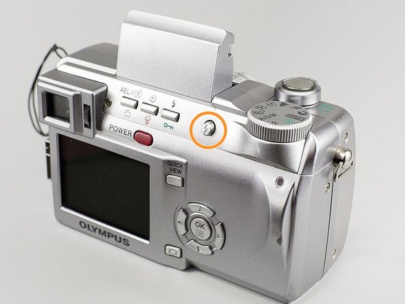
Use a Phillips #00 screwdriver to remove the single 4mm screw located directly to the right of the viewfinder on the back of the camera.
-
Remove the two 2mm screws from the left side panel.
-
Remove the single 3mm screw from the right side panel.
-
Remove the five 3mm screws from the bottom of the camera.
-
-
この手順は未翻訳です。 翻訳を手伝う。
-
Remove the ribbon cable directly below the viewfinder.
-
Detach the white plastic clip from its socket with a pair of tweezers.
-
Disconnect the ribbon cable from the center of the board, near the central hole.
-
Disconnect the three ribbon cables from the top right of the motherboard, near the selector wheel. One is on the top of the board, and the other two are on the underside.
-
-
-
この手順は未翻訳です。 翻訳を手伝う。
-
In order to access the flash assembly, you need to remove several interior components from the body of the camera.
-
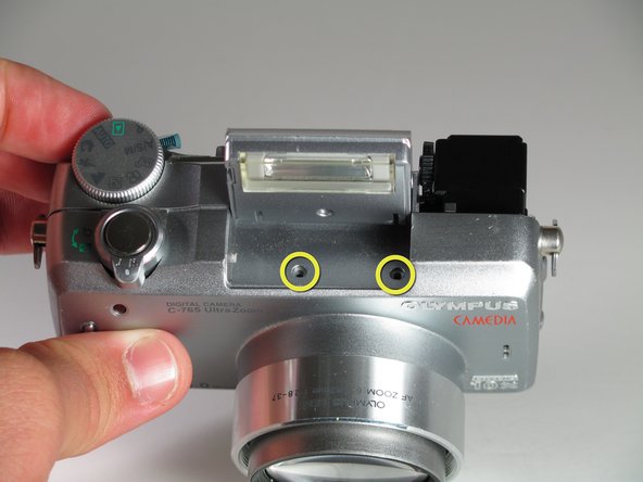
With a Phillips #00 screwdriver, unscrew the two 3mm screws from the right side of the casing.
-
Raise the flash by pressing the shutter button or lifting the flash up with your fingers to access the two body screws underneath.
-
Using the Phillips #00 screwdriver, unscrew the two 3mm screws by twisting counterclockwise.
-
-
この手順は未翻訳です。 翻訳を手伝う。
-
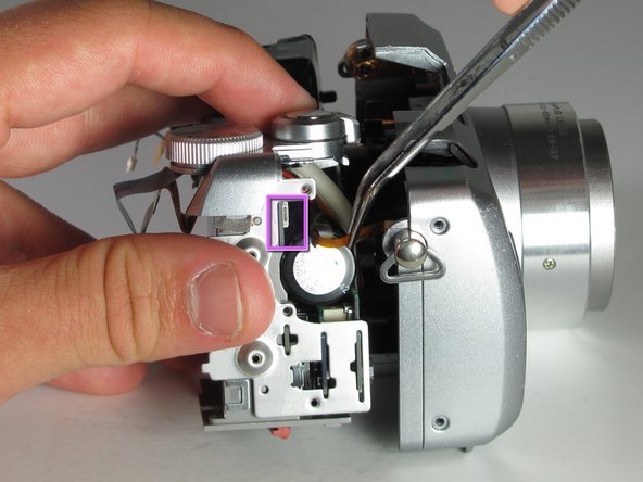
Gently pull the battery casing and the A/V ports away from the camera body to remove the connected components.
-
Using ESD Safe Blunt Nose Tweezers, gently remove the small ribbon cable from the right side of the casing
-
-
この手順は未翻訳です。 翻訳を手伝う。
-
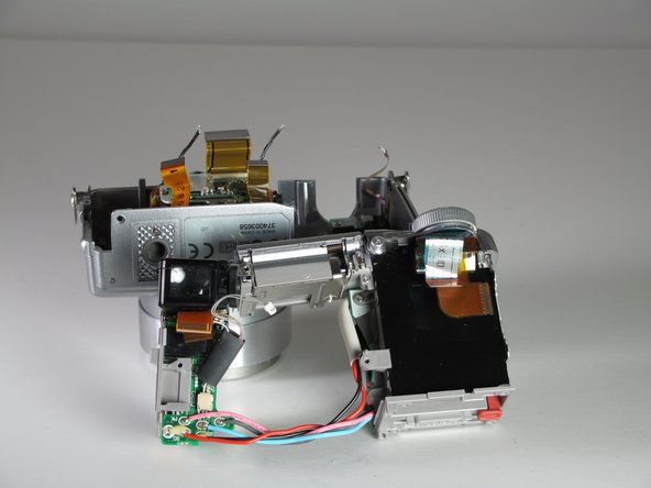
With a Phillips #00 screwdriver, unscrew the 3mm screw holding the flash assembly in place by twisting counter-clockwise.
-
Cut the wires running out from the flash assembly. When installing the new flash assembly, splice the new wires into the preexisting wires.
-
The camera is now ready for you to install a new flash assembly.
-


チーム

Cal Poly, Team 12-33, Maness Spring 2011 Cal Poly, Team 12-33, Maness Spring 2011人のメンバー
CPSU-MANESS-S11S12G33
3 メンバー
7のガイドは作成済み