メインコンテンツにスキップ

このバージョンは誤った内容を含んでいる可能性があります。最新の承認済みスナップショットに切り替えてください。

必要な工具と部品

  1. , バックカバーを外します: 手順 1、 3の画像 1 , バックカバーを外します: 手順 1、 3の画像 2 , バックカバーを外します: 手順 1、 3の画像 3
    • 再組み立てを始める前に、デバイスの電源を切ってください。

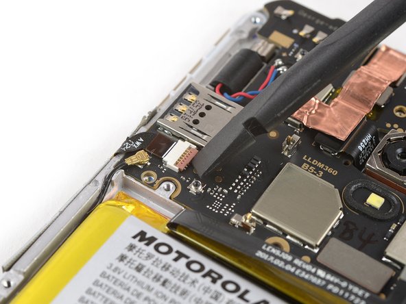
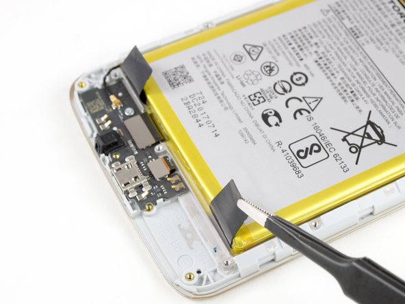
    • デバイス右側下のコーナー上にある溝にスパッジャーの先端を差し込みます。

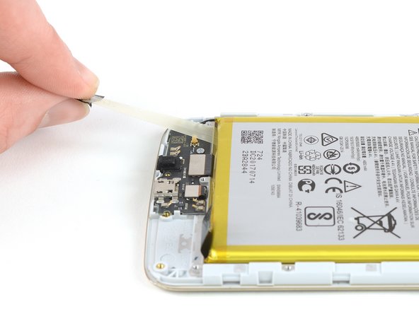
    • スパッジャーを捻って、デバイスからバックカバーを緩めます。

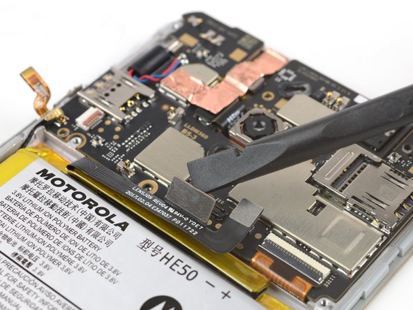
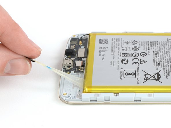
    • スパッジャーをデバイス下側端に沿ってスライドし、デバイスからバックカバーを外します。

  2. : 手順 2、 2の画像 1 : 手順 2、 2の画像 2
    • バックカバーからデバイスを持ち上げて取り出します。

  3. , ミッドフレーム: 手順 3、 1の画像 1
    • 3.3 mmプラスネジを18本外します。

  4. : 手順 4、 2の画像 1 : 手順 4、 2の画像 2
    • 充電ボードカバーの端を摘んで、持ち上げて取り出します。

  5. : 手順 5、 3の画像 1 : 手順 5、 3の画像 2 : 手順 5、 3の画像 3
    • バッテリーカバーの下側両端を掴んで、上向きに持ち上げます。

    • バッテリーカバーを取り出します。

  6. : 手順 6、 2の画像 1 : 手順 6、 2の画像 2
    • 開口ピックをマザーボードカバーの下側左のコーナーに差し込みます。

    • 開口ピックをカバーと2番目のSIMトレイの間にスライドして、プラスチッククリップを外します。

  7. : 手順 7、 2の画像 1 : 手順 7、 2の画像 2
    • 開口ピックをマザーボードカバー下側右のコーナーの下に差し込みます。

    • 開口ピックを使って、マザーボードカバーをこじ開けます。

  8. : 手順 8、 2の画像 1 : 手順 8、 2の画像 2
    • マザーボードカバーを取り出します。

  9. , バッテリーの接続を外します。: 手順 9、 2の画像 1 , バッテリーの接続を外します。: 手順 9、 2の画像 2
    • スパッジャーの先端を使って、マザーボードからバッテリーフレックスケーブルを持ち上げて接続を外します。

  10. この手順は未翻訳です。 翻訳を手伝う。

    : 手順 10、 1の画像 1
    • Remove the two 2.9 mm Phillips screws.

  11. この手順は未翻訳です。 翻訳を手伝う。

    : 手順 11、 3の画像 1 : 手順 11、 3の画像 2 : 手順 11、 3の画像 3
    • Use the edge of a spudger to pry up the flap of the ZIF connector located below the SIM slot on the left side of the motherboard.

    • Use a pair of tweezers to pull the power and volume button flex cable out of the ZIF connector.

    • To reattach ZIF connectors like this one, carefully insert the flex cable into the ZIF connector up to the marked line on the cable, and then close the locking flap.

  12. この手順は未翻訳です。 翻訳を手伝う。

    : 手順 12、 2の画像 1 : 手順 12、 2の画像 2
    • Use a pair of tweezers to pry up and disconnect the antenna cable.

  13. この手順は未翻訳です。 翻訳を手伝う。

    : 手順 13、 2の画像 1 : 手順 13、 2の画像 2
    • Use the flat end of a spudger to pry up and disconnect the interconnect flex cable.

  14. この手順は未翻訳です。 翻訳を手伝う。

    : 手順 14、 3の画像 1 : 手順 14、 3の画像 2 : 手順 14、 3の画像 3
    • Use the tip of a spudger or an opening pick to pry up the flap of the ZIF connector, located in the bottom right corner of the motherboard.

    • Use a pair of tweezers to pull the display flex cable out of the ZIF connector.

  15. この手順は未翻訳です。 翻訳を手伝う。

    : 手順 15、 2の画像 1 : 手順 15、 2の画像 2
    • Grasp the motherboard by the top corners and remove it by lifting up and pulling it carefully out of its recess.

  16. この手順は未翻訳です。 翻訳を手伝う。

    : 手順 16、 1の画像 1
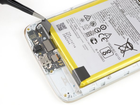
    • Apply a heated iOpener to the upper part of the phone for about 30 seconds to loosen the adhesive beneath the earpiece speaker.

  17. この手順は未翻訳です。 翻訳を手伝う。

    : 手順 17、 2の画像 1 : 手順 17、 2の画像 2
    • When removing the earpiece speaker with a pair of tweezers, take care to grab the whole unit. The earpiece speaker can easily break in two pieces if you only pull on its upper half.

    • Use a pair of tweezers to lift the earpiece speaker out of its recess and remove it.

    • When reassembling, be sure to properly orient the earpiece speaker such that the gold contacts are pointing away from the top edge.

  18. この手順は未翻訳です。 翻訳を手伝う。

    : 手順 18、 3の画像 1 : 手順 18、 3の画像 2 : 手順 18、 3の画像 3
    • Use a pair of tweezers to gently peel the power and volume button unit out of its thin recess on the left side of the frame.

    • Remove the power and volume button unit.

  19. この手順は未翻訳です。 翻訳を手伝う。

    : 手順 19、 3の画像 1 : 手順 19、 3の画像 2 : 手順 19、 3の画像 3
    • Use a pair of tweezers to peel the ends of the two pull tabs off of the bottom edge of the battery.

  20. この手順は未翻訳です。 翻訳を手伝う。

    : 手順 20、 3の画像 1 : 手順 20、 3の画像 2 : 手順 20、 3の画像 3
    • Pull out the left adhesive strip by steadily pulling the left tab at a flat angle.

    • If the adhesive strip rips, grab and twist the remaining stub around the tip of a pair of tweezers a couple of times and then continue pulling.

    • Repeat the same process for the right adhesive strip.

  21. この手順は未翻訳です。 翻訳を手伝う。

    : 手順 21、 2の画像 1 : 手順 21、 2の画像 2
    • Get a good grip on the battery and remove it.

  22. この手順は未翻訳です。 翻訳を手伝う。

    : 手順 22、 1の画像 1
    • Remove the single 2.9 mm Phillips screw holding the charging board to the frame.

  23. この手順は未翻訳です。 翻訳を手伝う。

    : 手順 23、 2の画像 1 : 手順 23、 2の画像 2
    • Use a pair of tweezers to pry up and disconnect the antenna cable and remove it.

  24. この手順は未翻訳です。 翻訳を手伝う。

    : 手順 24、 2の画像 1 : 手順 24、 2の画像 2
    • Use the edge of a spudger to pry up and disconnect the interconnect flex cable.

  25. この手順は未翻訳です。 翻訳を手伝う。

    : 手順 25、 2の画像 1 : 手順 25、 2の画像 2
    • Use the edge of a spudger to pry up and disconnect the fingerprint sensor flex cable.

  26. この手順は未翻訳です。 翻訳を手伝う。

    : 手順 26、 2の画像 1 : 手順 26、 2の画像 2
    • Insert the tip of a spudger underneath the bottom edge of the charging board and pry upwards.

    • Remove the charging board.

  27. この手順は未翻訳です。 翻訳を手伝う。

    : 手順 27、 2の画像 1 : 手順 27、 2の画像 2
    • Use a pair of tweezers to gently peel the interconnect flex cable from the frame and remove it.

  28. この手順は未翻訳です。 翻訳を手伝う。

    : 手順 28、 1の画像 1
    • The bare screen with frame remains.

    • Before reassembly, check your new part for any components like gaskets, that might need to be transferred from the old one.

ゴール

3 の人々がこのガイドを完成させました。

作成者

4人の作成者と共同で作成されました。

Dominik Schnabelrauch

メンバー登録日: 11/23/16

203,728 ポイント

682のガイドは作成済み

チーム

iFixit iFixit人のメンバー

Staff

135 メンバー

17,182のガイドは作成済み

2 件のコメント

Bonjour cher ami

Grace a vous je me suis lancé dans le remplacement de mon ecran explosé par le passage d’un véhicule. j’ai suivi vos explications a la lettre dans le démontage et pour le remontage aussi vous n’avez pas signalé de récupérer le revêtement de cuivre, j’ai réussi de le décoller en chauffant. Tout fonctionne comme avant.

Merci de ce tuto. Félicitations.

henri perrin - 返信

Thanks for your comment. Glad to hear you could get it back to working conditions. Welcome to the club of fixers.

Tobias Isakeit -

コメントを追加

統計データ:

過去 24時間: 2

過去 7 日: 18

過去 30 日: 39

今までの合計 5,487