はじめに
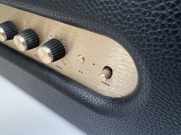
This guide is intended to replace the power switch assembly in the Marshall Stanmore II Bluetooth Speaker.
The power switch turns the speaker on or off while it is plugged into a wall outlet. Over time, the power switch may break or wear down after normal use. This renders the speaker inoperable.
Before using this guide, ensure the speaker is plugged into a working outlet. This can be verified by plugging another device and ensuring that it works as intended. After verifying the outlet, follow the "Failure to power on" section of the Marshall Stanmore II troubleshooting page.
必要な工具と部品
-
-
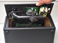
Lay the speaker with the back panel facing up on a flat, stable work surface.
 FixBotに聞いてみる
-
-
-
Use a Phillips #2 screwdriver to remove the ten 20.5 mm screws that secure the rear panel to the chassis.
-
-
-
-
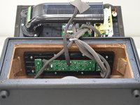
Carefully lift the rear panel and let it rest on an object, like a stack of books, to avoid straining the cables.
-
-
-
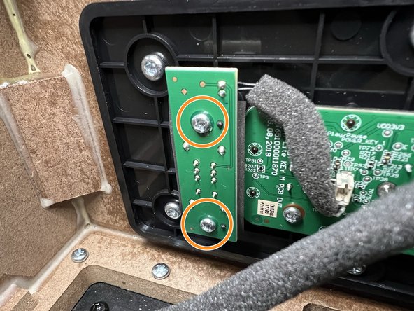
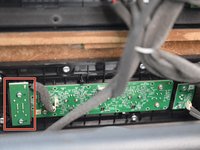
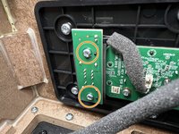
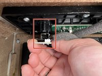
Locate the Power Switch PCB on the left-hand side above the subwoofer.
-
Use a Phillips #2 screwdriver to remove the two 10 mm screws that secure the PCB.
-


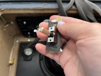
To reassemble your device, follow these instructions in reverse order.
3 の人々がこのガイドを完成させました。

チーム

University of North Texas, Team 2-1, Kilpatrick Spring 2024 University of North Texas, Team 2-1, Kilpatrick Spring 2024人のメンバー
UNT-KILPATRICK-S24S2G1
5 メンバー
6のガイドは作成済み