メインコンテンツにスキップ

Mainboard Assembly

必要条件のみ
この修理ガイドは、他のガイドの前提条件として使用されます。それ自体は不完全で、単独で使用されることはありません。

必要な工具と部品

  1. Mainboard Assembly, Unfasten the back cover screws: 手順 1、 1の画像 1
    • Use a Phillips #00 screwdriver to remove the four 11 mm-long screws securing the back cover.

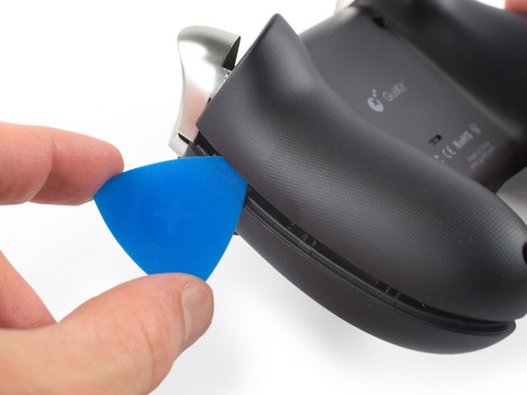
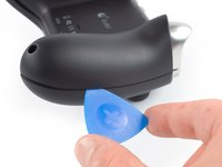
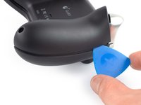
  2. Mainboard Assembly, Insert an opening pick: 手順 2、 2の画像 1 Mainboard Assembly, Insert an opening pick: 手順 2、 2の画像 2
    • The back cover of the GuliKit Kingkong 2 Pro is held in place by plastic clips.

    • Insert an opening pick into the gap between the front assembly and the back cover at the bottom edge of the controller.

    • Tilt your opening pick downwards to widen the gap.

  3. Mainboard Assembly, Separate the front assembly and back cover: 手順 3、 2の画像 1 Mainboard Assembly, Separate the front assembly and back cover: 手順 3、 2の画像 2
    • Insert an opening pick into the gap between the front assembly and the back cover at the outside of the right controller handle.

    • Slide the opening pick along the gap to separate the front assembly from the back cover.

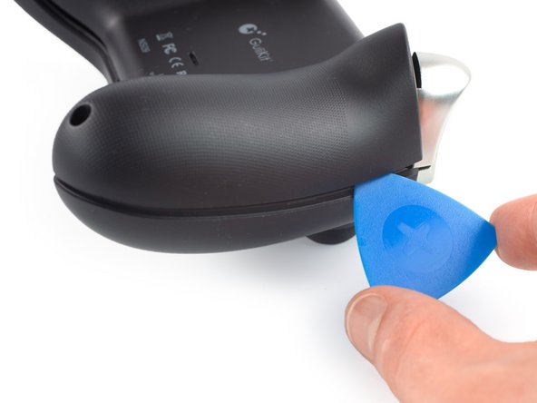
  4. Mainboard Assembly: 手順 4、 2の画像 1 Mainboard Assembly: 手順 4、 2の画像 2
    • Insert an opening pick into the gap between the front assembly and the back cover at the outside of the left controller handle.

    • Slide the opening pick along the gap to separate the front assembly from the back cover.

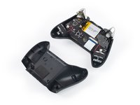
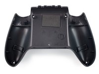
  5. Mainboard Assembly, Remove the back cover: 手順 5、 2の画像 1 Mainboard Assembly, Remove the back cover: 手順 5、 2の画像 2
    • Separate the back cover from the front assembly and remove it.

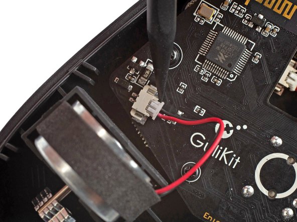
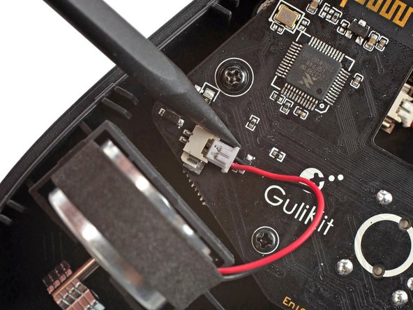
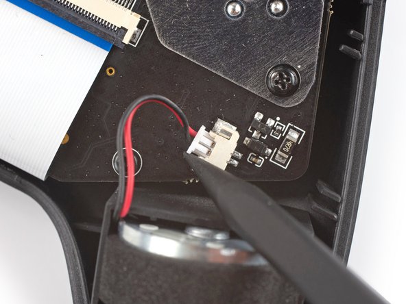
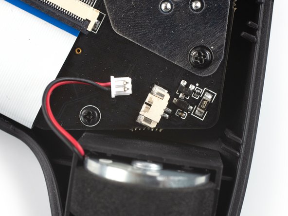
  6. Mainboard Assembly, Disconnect the right vibration motor: 手順 6、 3の画像 1 Mainboard Assembly, Disconnect the right vibration motor: 手順 6、 3の画像 2 Mainboard Assembly, Disconnect the right vibration motor: 手順 6、 3の画像 3
    この手順で使用する道具:
    Tweezers
    $4.99
    購入する
    • It's not mandatory to remove the two vibration motors to remove the mainboard assembly. However, other repairs become much easier with the motors removed. If you want to leave the motors in place, you can jump straight to step 9.

    • Pull on the connectors themselves and not the cables to avoid damaging them.

    • Use the point of a spudger to disconnect the right vibration motor by pushing the connector straight out of its socket.

    • If you can't disconnect the vibration motor with a spudger, use a pair of blunt nose tweezers to pull the connector out of its socket.

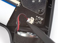
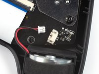
  7. Mainboard Assembly, Disconnect the left vibration motor: 手順 7、 3の画像 1 Mainboard Assembly, Disconnect the left vibration motor: 手順 7、 3の画像 2 Mainboard Assembly, Disconnect the left vibration motor: 手順 7、 3の画像 3
    • Use the point of a spudger to disconnect the left vibration motor by pushing the connector straight out of its socket.

  8. Mainboard Assembly, Remove the vibration motors: 手順 8、 1の画像 1
    • Remove the vibration motors by lifting them out of the controller housing.

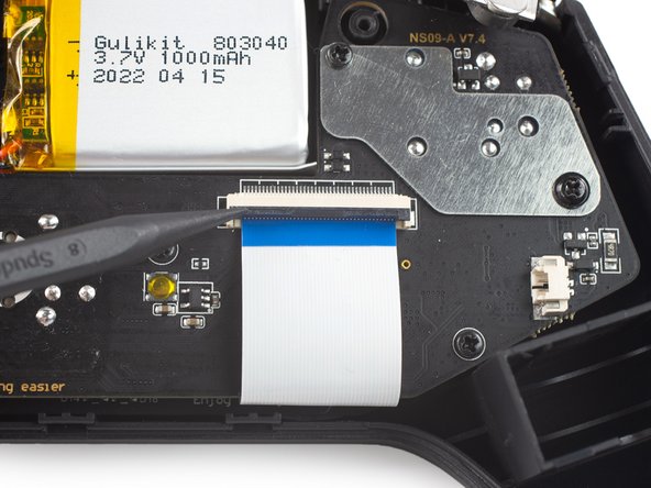
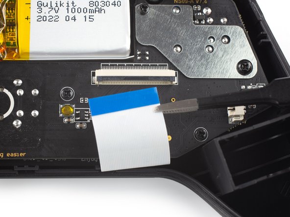
  9. Mainboard Assembly, Release the interconnect cable ZIF connector: 手順 9、 2の画像 1 Mainboard Assembly, Release the interconnect cable ZIF connector: 手順 9、 2の画像 2
    • Use a spudger, an opening tool, or your fingernail to flip up the small, hinged locking flap on the interconnect cable's ZIF connector.

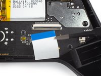
  10. Mainboard Assembly, Disconnect the interconnect cable: 手順 10、 2の画像 1 Mainboard Assembly, Disconnect the interconnect cable: 手順 10、 2の画像 2
    • Use a pair of blunt nose tweezers to disconnect the interconnect cable by pulling the cable straight out of the connector.

  11. Mainboard Assembly, Unfasten the mainboard assembly screws: 手順 11、 1の画像 1
    • Use a Phillips #00 screwdriver to remove the screws securing the mainboard assembly:

    • Four 7.8 mm-long screws.

    • Two 11 mm-long screws.

  12. Mainboard Assembly, Remove the mainboard shield: 手順 12、 2の画像 1 Mainboard Assembly, Remove the mainboard shield: 手順 12、 2の画像 2
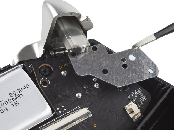
    • Use a pair of blunt nose tweezers to remove the metal shield from the mainboard assembly.

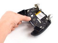
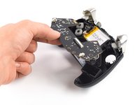
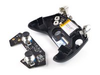
  13. Mainboard Assembly, Remove the mainboard assembly: 手順 13、 3の画像 1 Mainboard Assembly, Remove the mainboard assembly: 手順 13、 3の画像 2 Mainboard Assembly, Remove the mainboard assembly: 手順 13、 3の画像 3
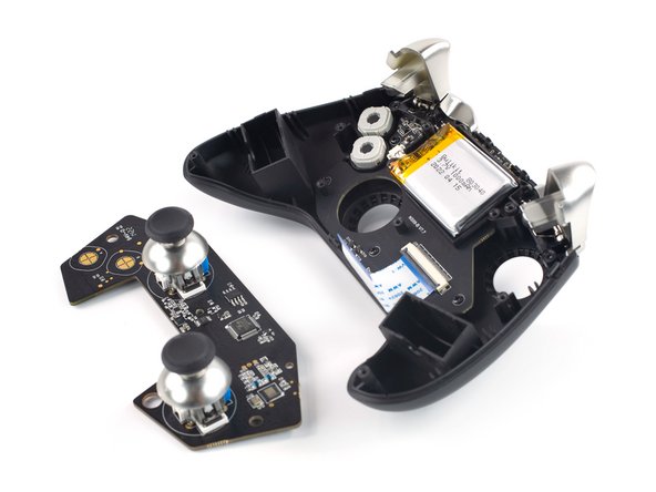
    • Remove the mainboard assembly by lifting it out of the controller housing.

終わりに

To reassemble your device, follow these instructions in reverse order.

作成者

2人の作成者と共同で作成されました。

Dominik Schnabelrauch

メンバー登録日: 11/23/16

209,102 ポイント

682のガイドは作成済み

チーム

iFixit iFixit人のメンバー

Staff

141 メンバー

17,813のガイドは作成済み

0 件のコメント

コメントを追加

統計データ:

過去 24時間: 1

過去 7 日: 3

過去 30 日: 12

今までの合計 215