はじめに
Use this guide to replace the Touch ID sensor/power button in your MacBook Air 15" 2024.
You may need to replace the Touch ID sensor/power button if it's unresponsive, inconsistent, or physically damaged.
To maintain Touch ID functionality, you must also replace your logic board with a new one that's paired to the replacement Touch ID sensor. The MacBook Air's original Touch ID sensor is uniquely paired to the logic board at the factory. Without Apple’s proprietary calibration process, even a genuine replacement logic board from another MacBook Air won’t work.
必要な工具と部品
-
-
Unplug all cables and fully power off your MacBook.
-
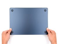
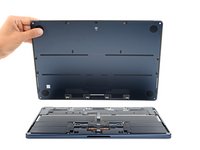
Close the display and lay your MacBook upside down. Keep your laptop closed until you've physically disconnected the battery.
-
-
この手順で使用する道具:FixMat$36.95
-
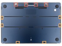
Use a P5 pentalobe screwdriver to remove the four 6.4 mm‑long screws securing the lower case.
-
-
-
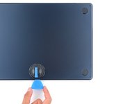
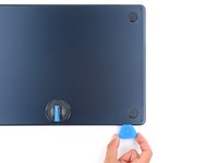
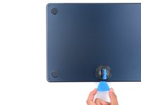
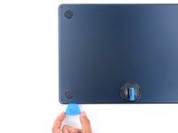
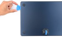
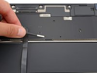
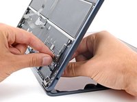
Apply a suction handle to the center of the lower case's front edge.
-
Pull up on the suction handle to create a gap between the lower case and the frame.
-
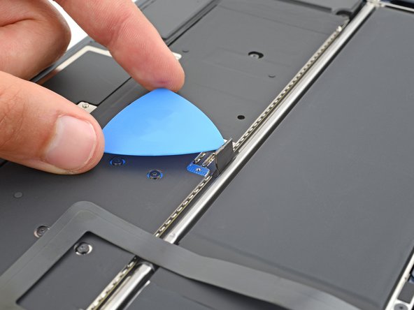
Insert an opening pick into the gap.
-
-
-
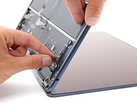
Slide the pick to the bottom right corner to release the first clip.
-
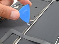
Slide the pick around the corner and up the right edge to release the next two clips.
-
-
-
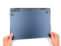
Keep the lower case flat to the frame and firmly slide it straight away from the back edge, one corner at a time, to disengage the sliding tabs.
-
-
-
Remove the lower case.
-
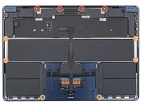
Set the lower case in place and align the sliding tabs with the screw heads they slide over. Press down and slide the lower case toward the back edge to engage the tabs—it'll stop sliding as the tabs engage.
-
Once the lower case is flush with the frame, press down firmly along the perimeter to engage the six snapping clips.
-
-
この手順で使用する道具:Tweezers$4.99
-
Use blunt nose tweezers or your fingers to remove the piece of tape covering the battery connector cover.
-
-
-
Use a 3IP Torx Plus screwdriver to remove the two 1.5 mm‑long screws securing the battery connector cover.
-
Remove the cover.
-
-
-
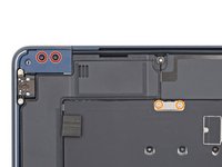
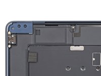
Use a 3IP Torx Plus screwdriver to remove the following screws:
-
Two 2.6 mm‑long screws securing the left hinge cover
-
Two 1.5 mm‑long screws securing the speaker cable cover
-
-
-
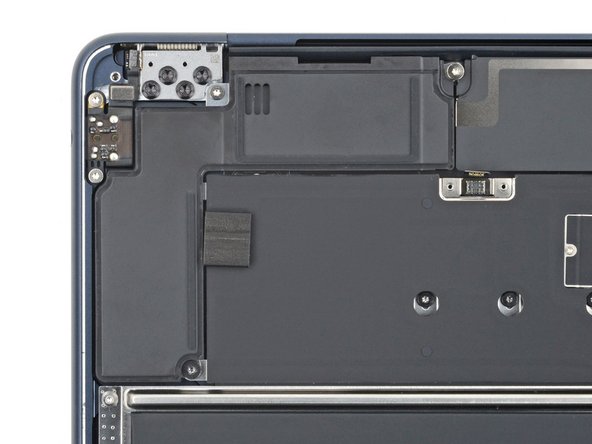
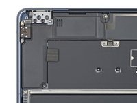
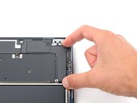
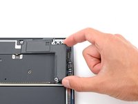
Use the point of a spudger to pry up and disconnect the right speaker press connector.
-
-
-
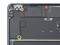
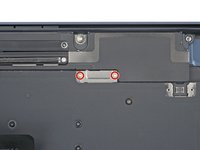
Remove the three screws securing the right speaker:
-
One 5.5 mm‑long 4IP Torx Plus screw
-
One 2.7 mm‑long 4IP Torx Plus screw
-
One 3.5 mm‑long 6IP Torx Plus screw
-
-
-
-
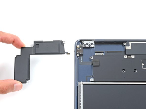
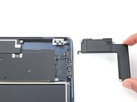
Lift the speaker's left edge over the frame and slide it to the left to remove it.
-
-
-
Use a 3IP Torx Plus screwdriver to remove the following screws:
-
Two 2.6 mm‑long screws securing the right hinge cover
-
Two 1.5 mm‑long screws securing the speaker cable cover
-
-
-
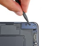
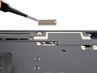
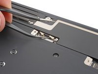
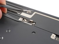
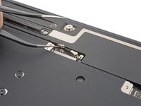
Insert the point of a spudger into one of the right hinge cover's screw holes.
-
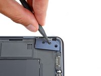
Push the hinge cover away from the back edge to dislodge it.
-
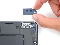
Remove the hinge cover.
-
-
-
Use the point of a spudger to pry up and disconnect the left speaker press connector.
-
-
-
Remove the three screws securing the right speaker:
-
One 5.5 mm‑long 4IP Torx Plus screw
-
One 2.7 mm‑long 4IP Torx Plus screw
-
One 3.5 mm‑long 6IP Torx Plus screw
-
-
-
Lift the speaker's right edge over the frame and slide it to the right to remove it.
-
-
-
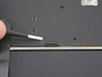
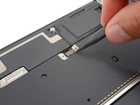
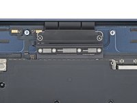
Use a 3IP Torx Plus screwdriver to remove the two 1.5 mm‑long screws securing the antenna cables cover.
-
Remove the cover.
-
-
この手順で使用する道具:Tweezers$3.99
-
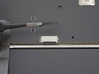
Insert one arm of a pair of angled tweezers under the metal neck of one of the antenna connectors and lift straight up to disconnect it.
-
Disconnect the other antenna.
-
-
-
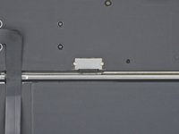
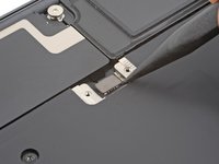
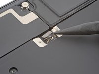
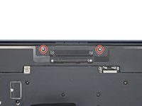
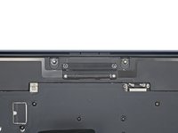
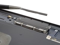
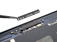
Use a 4IP Torx Plus screwdriver to remove the two 5.5 mm‑long screws securing the antenna bar.
-
-
この手順で使用する道具:Tesa 61395 Tape$2.99
-
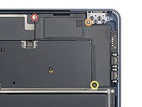
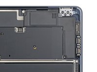
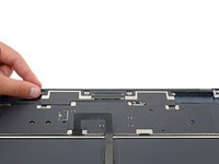
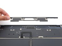
Use tweezers or your fingers to remove the foam pad from the cover.
-
-
-
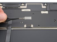
Use a 3IP Torx Plus screwdriver to remove the four 1.5 mm‑long screws securing the display and camera cables cover.
-
Remove the cover.
-
-
-
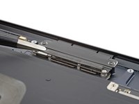
Use a spudger to pry up and disconnect the display and camera cable press connectors.
-
-
-
Use a 3IP Torx Plus screwdriver to remove the two 2.8 mm‑long screws securing the display and camera cables to the frame.
-
-
この手順で使用する道具:Tweezers$4.99
-
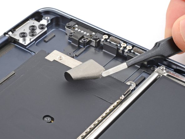
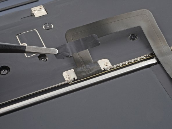
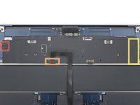
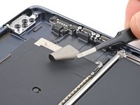
Use blunt nose tweezers or your fingers to remove the foam pad and two pieces of tape:
-
The headphone jack press connector cover's foam pad
-
The trackpad cable tape
-
The MagSafe and Thunderbolt connector cover tape
-
-
この手順で使用する道具:Tesa 61395 Tape$2.99
-
Pull the trackpad cable away from its cover to separate the adhesive securing it.
-
-
-
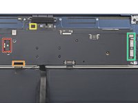
Use a 3IP Torx Plus screwdriver to remove the six 1.5 mm‑long screws securing the interconnect, trackpad, and MagSafe/Thunderbolt connector covers.
-
Remove the three connector covers.
-
-
-
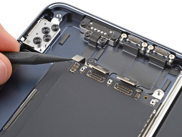
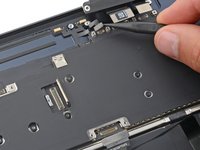
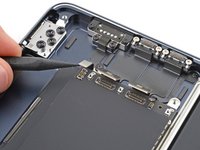
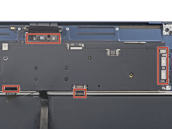
Use a spudger to pry up and disconnect all seven press connectors from the logic board:
-
One for the interconnect cable
-
One for the trackpad cable
-
One for the microphone array cable
-
Four on the right side of the logic board for the MagSafe, Thunderbolt and Hall effect sensor cables
-
-
-
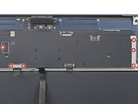
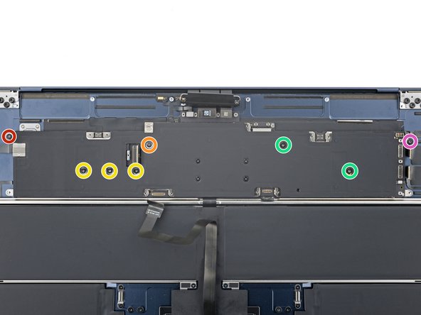
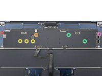
Use a 3IP Torx Plus screwdriver to remove the two screws on the upper left edge of the logic board:
-
One 2.6 mm‑long screw
-
One 4.7 mm‑long screw
-
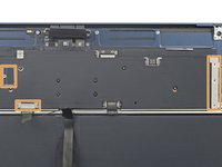
Use a 5IP Torx Plus screwdriver to remove the six remaining screws securing the logic board:
-
Three 3.1 mm‑long screws
-
Two 3.8 mm‑long screws
-
One 3.6 mm‑long screw
-
-
-
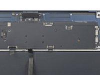
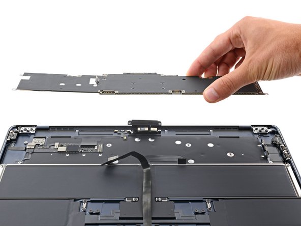
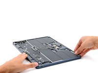
Grip the right side of the logic board and remove it.
-
Lower the logic board into place, making sure no cables get stuck underneath.
-
Carefully check the edges of the logic board to see if any cables got stuck underneath. If any did, use the point of a spudger to gently pull them out.
-
-
-
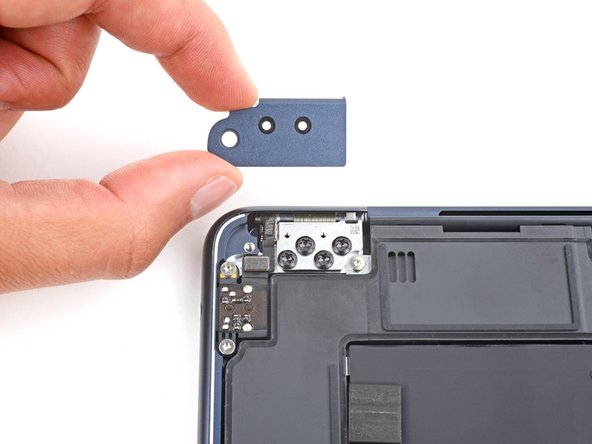
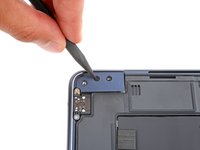
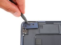
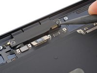
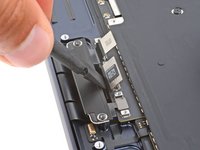
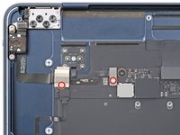
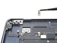
Use a 3IP Torx Plus screwdriver to remove the two 1.5 mm‑long screws securing the Touch ID sensor and headphone jack connector covers.
-
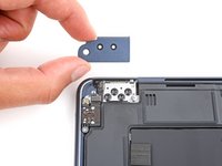
Remove the two covers.
-
-
-
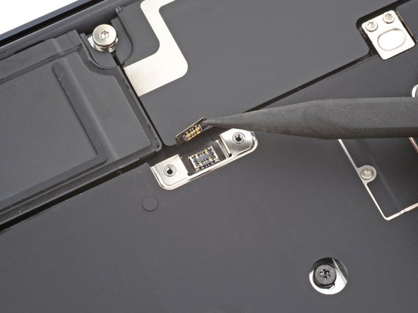
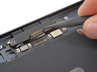
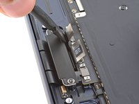
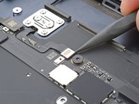
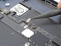
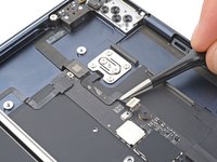
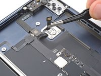
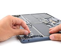
Use a spudger to pry up and disconnect the Touch ID sensor press connector from the daughterboard.
-
-
この手順で使用する道具:Tesa 61395 Tape$2.99
-
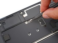
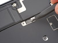
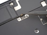
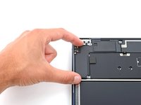
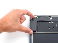
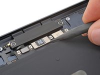
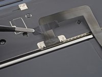
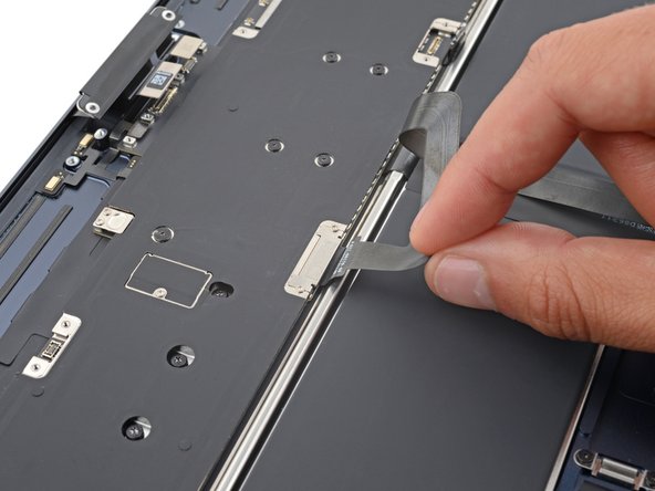
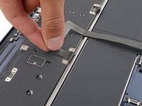
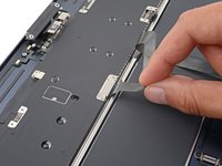
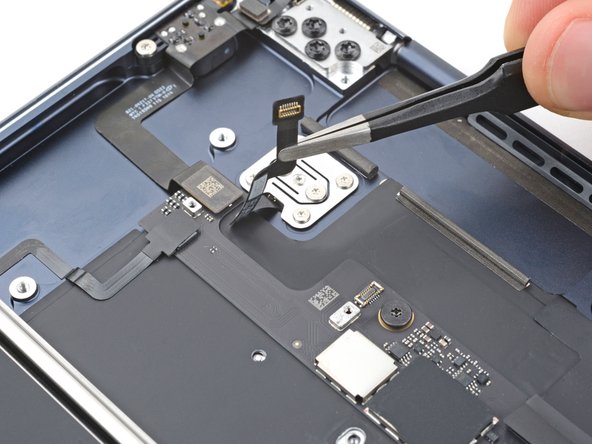
Use blunt-nose tweezers or your fingers to peel the Touch ID sensor cable from the frame.
-
If your new Touch ID sensor's cable comes with adhesive, remove the plastic liner and press the cable into place on the frame.
-
If the cable doesn't have adhesive, use a strip of double-sided tape to secure it to the frame.
-
-
-
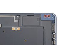
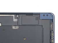
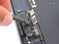
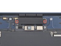
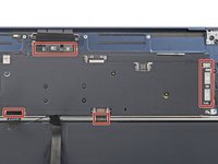
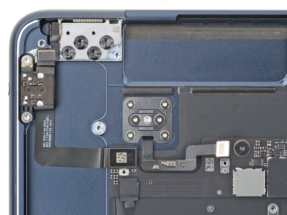
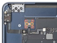
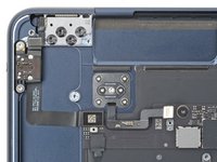
Use a 3IP Torx Plus screwdriver to remove the six screws securing the Touch ID sensor and its bracket:
-
Four 2 mm‑long screws
-
Two 1.7 mm‑long screws
-
Install the screws without fully tightening them.
-
Open your MacBook and align the Touch ID sensor on the keyboard.
-
Close your MacBook and fully tighten the screws.
-
-
-
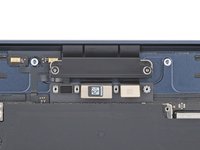
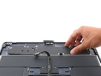
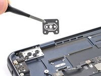
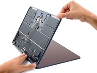
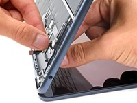
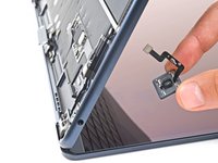
Pull the Touch ID sensor away from the frame while guiding the cable through its slot.
-
Remove the sensor.
-
-
-
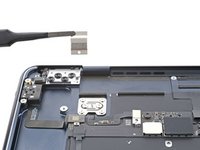
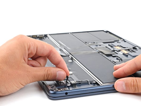
Guide the new Touch ID sensor's cable through its slot in the fame.
-
Hold the cable with one hand and use your other hand to align the new sensor in its recess.
-
Once the sensor is aligned, gently pull the cable away from the MacBook to secure the sensor against the frame.
-
Continue holding the sensor in place by its cable and slowly close the MacBook.
-


To reassemble your device, follow these instructions in reverse order.
Take your e-waste to an R2 or e-Stewards certified recycler.
Repair didn’t go as planned? Try some basic troubleshooting, or ask our Answers community for help.
To reassemble your device, follow these instructions in reverse order.
Take your e-waste to an R2 or e-Stewards certified recycler.
Repair didn’t go as planned? Try some basic troubleshooting, or ask our Answers community for help.

