はじめに
This guide will show you how to disassemble your Wave Beam aka Vibe Beam earbuds case and replace a dead battery.
Although a Vibe Beam case is shown, these steps should work with other JBL cases that use a similar design.
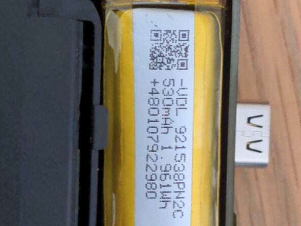
If you want to order a battery, it needs to be 3.7v and smaller than 10mm x 14mm x 40mm. This aliexpress listing should do the job:
https://www.aliexpress.com/item/10050097...
必要な工具と部品
-
-
Open up your case and remove the earbuds. Prepare a heat gun at around 150℃, and gently heat up the front part of the case, around where the LED is.
 FixBotに聞いてみる
-
-
-
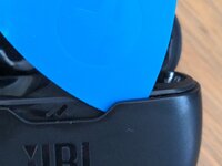
Now try to insert an opening pick into the seam as shown. If you can't get it in, try heating the case more or using a different pick.
-
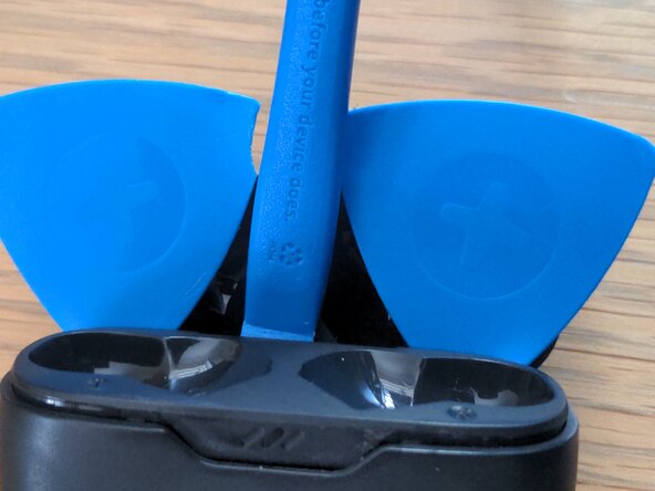
Slide the pick around the edge of the case until it reaches the back, next to the hinge part. You can apply more heat here if this is too difficult.
-
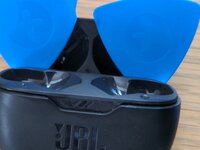
Repeat with a second opening pick, going round the other side. The second image shows what your case should now look like.
-
-
-
-
Use a plastic tool to lift up the internals as shown
-
If this is too difficult, you might want to use a third pick, and pry around the area under the LED.
-
-
-
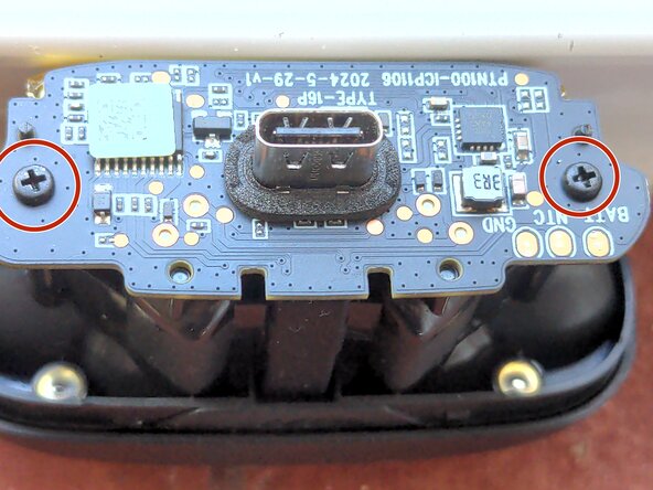
You should now have removed the outer case. Remove the two Phillips #0 screws next to the exposed USB port.
-
Pull the motherboard directly upwards. Be gentle here, as it is still connected to the glued-down battery
-
Use a plastic tool to pry out the battery, it is attached to the case with a sticky pad. If you have isopropyl alcohol, apply some underneath the battery to loosen the adhesive.
-
-
-
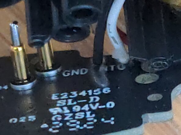
The battery is connected to the motherboard with either 3 or 2 solder pads. Use a soldering iron and flux to remove all of them, being careful not to cause any shorts.
-
-
-
Solder the black and red wires of your new battery to GND and BATT on the motherboard, respectively. If there is a third wire (temperature sensor) solder it to the NTC pad.
-


To reassemble your device, follow these instructions in reverse order.
2 の人々がこのガイドを完成させました。