メインコンテンツにスキップ

Insignia Flex 10.1 NS-P10A6100 Motherboard Replacement

必要な工具と部品

  1. Insignia Flex 10.1 NS-P10A6100 Motherboard Replacement, Back Case: 手順 1、 1の画像 1
    • Make sure your tablet is turned off and not connected to a power source to prevent personal injury.

    • The volume rocker and power button located on the top edge by the camera are not connected pieces and will become free from the device once the front panel is removed from the back case. They are easily put back in place when reassembling the tablet.

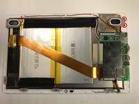
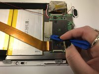
    • Position the tablet with the top edge by the camera facing down.

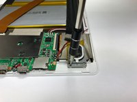
    • Insert the plastic opening tool between the front panel and back case at the upper left hand corner of the tablet.

  2. Insignia Flex 10.1 NS-P10A6100 Motherboard Replacement: 手順 2、 2の画像 1 Insignia Flex 10.1 NS-P10A6100 Motherboard Replacement: 手順 2、 2の画像 2
    • Slide the plastic opening tool along the edge of the tablet between the front panel and back case.

    • Repeat this process for the two shorter edges of the tablet leaving the top edge by the camera still snapped in place.

  3. Insignia Flex 10.1 NS-P10A6100 Motherboard Replacement: 手順 3、 1の画像 1
    • Using an unfolding motion along the top edge of the tablet, carefully separate the front panel from the back case.

  4. Insignia Flex 10.1 NS-P10A6100 Motherboard Replacement, Motherboard: 手順 4、 1の画像 1
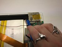
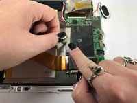
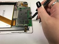
    • Using the plastic opening tool, lift up the black retaining flap that secures the camera ZIF (zero insertion force) ribbon connector to the motherboard

  5. Insignia Flex 10.1 NS-P10A6100 Motherboard Replacement: 手順 5、 1の画像 1
    • Pull the ZIF (zero insertion force) ribbon connector out from underneath the black retaining flap.

  6. Insignia Flex 10.1 NS-P10A6100 Motherboard Replacement: 手順 6、 1の画像 1
    • Using the plastic opening tool, lift up the black retaining flap that secures the ZIF (zero insertion force) ribbon connector over the battery to the motherboard.

  7. Insignia Flex 10.1 NS-P10A6100 Motherboard Replacement: 手順 7、 1の画像 1
    • Pull the ZIF (zero insertion force) ribbon connector out from underneath the black retaining flap.

  8. Insignia Flex 10.1 NS-P10A6100 Motherboard Replacement: 手順 8、 1の画像 1
    • Using the plastic opening tool, lift up the black retaining flap that secures the volume and power button ZIF (zero insertion force) ribbon connector to the motherboard.

  9. Insignia Flex 10.1 NS-P10A6100 Motherboard Replacement: 手順 9、 1の画像 1
    • Pull the ZIF (zero insertion force) ribbon connector out from underneath the black retaining flap.

  10. Insignia Flex 10.1 NS-P10A6100 Motherboard Replacement: 手順 10、 2の画像 1 Insignia Flex 10.1 NS-P10A6100 Motherboard Replacement: 手順 10、 2の画像 2
    • Using the Phillips #000 screw driver, unscrew the two 4 mm screws securing the right speaker to the front panel in a counterclockwise direction.

    • The two screws are very small, so be careful not to lose them after unscrewing them.

  11. Insignia Flex 10.1 NS-P10A6100 Motherboard Replacement: 手順 11、 2の画像 1 Insignia Flex 10.1 NS-P10A6100 Motherboard Replacement: 手順 11、 2の画像 2
    • Using the plastic opening tool, remove the silver tape covering the display ZIF (zero insertion force) ribbon connector.

  12. Insignia Flex 10.1 NS-P10A6100 Motherboard Replacement: 手順 12、 1の画像 1
    • Using the plastic opening tool, lift up the black retaining flap that secures the display ZIF (zero insertion force) ribbon connector to the motherboard.

  13. Insignia Flex 10.1 NS-P10A6100 Motherboard Replacement: 手順 13、 1の画像 1
    • Pull the ZIF (zero insertion force) ribbon connector out from underneath the black retaining flap.

  14. Insignia Flex 10.1 NS-P10A6100 Motherboard Replacement: 手順 14、 1の画像 1
    • Desoldering can cause fumes that are dangerous to breathe in, and materials may be hot.

    • Desolder the four joints connecting the red and black wires from the speakers to the motherboard.

    • A thorough guide including step by step instructions on how to solder and desolder can be found here.

  15. Insignia Flex 10.1 NS-P10A6100 Motherboard Replacement: 手順 15、 1の画像 1
    • Desoldering can cause fumes that are dangerous to breathe in, and materials may be hot.

    • Desolder the three joints connecting the red, black, and white wires from the battery to the motherboard.

    • A thorough guide including step by step instructions on how to solder and desolder can be found here.

  16. Insignia Flex 10.1 NS-P10A6100 Motherboard Replacement: 手順 16、 2の画像 1 Insignia Flex 10.1 NS-P10A6100 Motherboard Replacement: 手順 16、 2の画像 2
    • Using the plastic opening tool, remove the silver tape that secures the motherboard to the front panel.

  17. Insignia Flex 10.1 NS-P10A6100 Motherboard Replacement: 手順 17、 2の画像 1 Insignia Flex 10.1 NS-P10A6100 Motherboard Replacement: 手順 17、 2の画像 2
    • Using the Phillips #000 screw driver, unscrew the three 4 mm screws securing the motherboard to the front panel in a counterclockwise direction.

    • The three screws are very small, so be careful not to lose them after unscrewing them.

終わりに

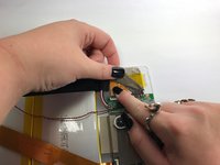
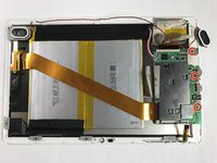
The motherboard is now free from the device and can now be replaced. To reassemble your device, follow these instructions in reverse order.

3 の人々がこのガイドを完成させました。

作成者

2人の作成者と共同で作成されました。

Samantha Damewood

メンバー登録日: 10/29/16

961 ポイント

5のガイドは作成済み

チーム

Baylor, Team 5-8, Williams Fall 2016 Baylor, Team 5-8, Williams Fall 2016人のメンバー

BU-WILLIAMS-F16S5G8

3 メンバー

12のガイドは作成済み

コメント 1 件

где можно приобрести такую плату

Александр к - 返信

コメントを追加

統計データ:

過去 24時間: 0

過去 7 日: 0

過去 30 日: 1

今までの合計 1,007