メインコンテンツにスキップ
リペアコミュニティに参加 - アカウントの作成

Hover-1 Horizon Left Gyroscope Sensor Board Replacement

必要な工具と部品

    1. Hover-1 Horizon Left Gyroscope Sensor Board Replacement, Base Plate: 手順 1、 2の画像 1 Hover-1 Horizon Left Gyroscope Sensor Board Replacement, Base Plate: 手順 1、 2の画像 2
      • Remove the six 12mm Phillips #2 screws holding the base plate.

      FixBotに聞いてみる

      コメントを追加

    2. Hover-1 Horizon Left Gyroscope Sensor Board Replacement: 手順 2、 2の画像 1 Hover-1 Horizon Left Gyroscope Sensor Board Replacement: 手順 2、 2の画像 2
      • Remove the two 11mm Phillips #1 screws that hold the base plate to the body.

      FixBotに聞いてみる
      コメントを追加

    3. Hover-1 Horizon Left Gyroscope Sensor Board Replacement: 手順 3、 3の画像 1 Hover-1 Horizon Left Gyroscope Sensor Board Replacement: 手順 3、 3の画像 2 Hover-1 Horizon Left Gyroscope Sensor Board Replacement: 手順 3、 3の画像 3
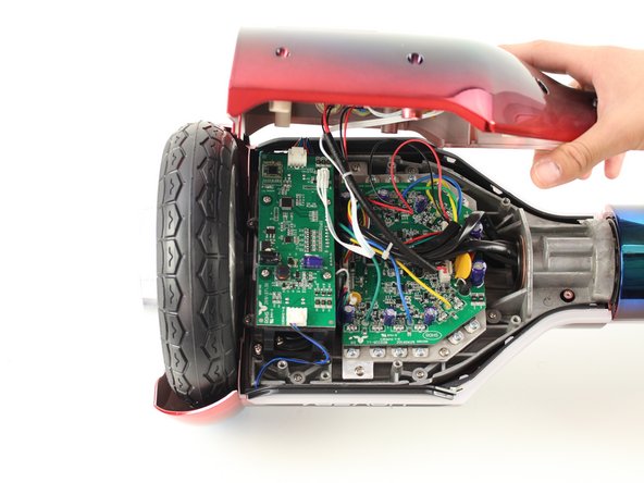
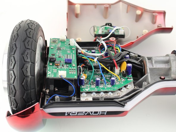
      • Remove the base plate by lifting it up.

      • The base plate is connected to the body with wires. The wires are long enough to set the base plate to the side.

      FixBotに聞いてみる
      コメントを追加

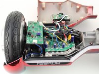
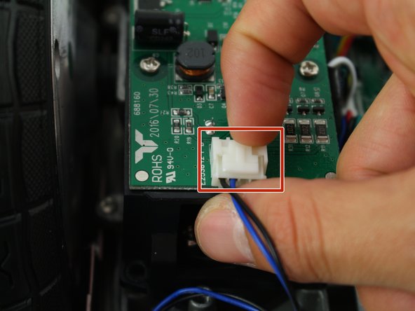
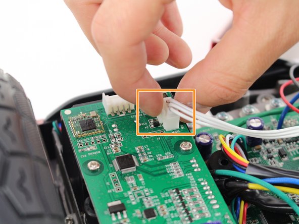
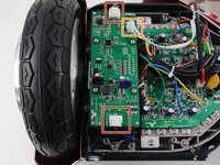
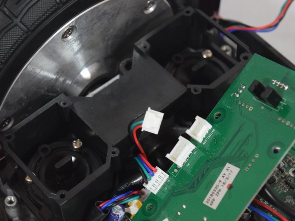
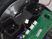
    1. Hover-1 Horizon Left Gyroscope Sensor Board Replacement, Left Gyroscope Sensor Board: 手順 4、 3の画像 1 Hover-1 Horizon Left Gyroscope Sensor Board Replacement, Left Gyroscope Sensor Board: 手順 4、 3の画像 2 Hover-1 Horizon Left Gyroscope Sensor Board Replacement, Left Gyroscope Sensor Board: 手順 4、 3の画像 3
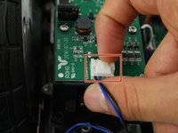
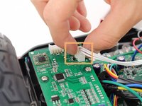
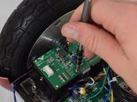
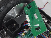
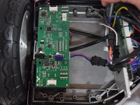
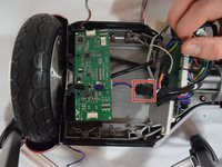
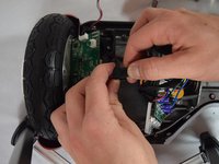
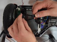
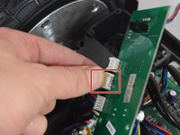
      • Remove the two connectors on either side of the board by lifting the tab and pulling out.

      • Remove the connector in the middle of the board by squeezing the tab and pulling up.

      FixBotに聞いてみる
      コメントを追加

    2. Hover-1 Horizon Left Gyroscope Sensor Board Replacement: 手順 5、 2の画像 1 Hover-1 Horizon Left Gyroscope Sensor Board Replacement: 手順 5、 2の画像 2
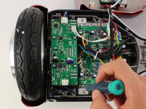
      • Remove the four 11mm Phillips #1 screws that hold the cover on.

      FixBotに聞いてみる

      コメントを追加

    3. Hover-1 Horizon Left Gyroscope Sensor Board Replacement: 手順 6、 3の画像 1 Hover-1 Horizon Left Gyroscope Sensor Board Replacement: 手順 6、 3の画像 2 Hover-1 Horizon Left Gyroscope Sensor Board Replacement: 手順 6、 3の画像 3
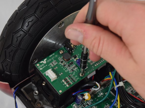
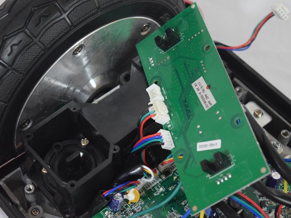
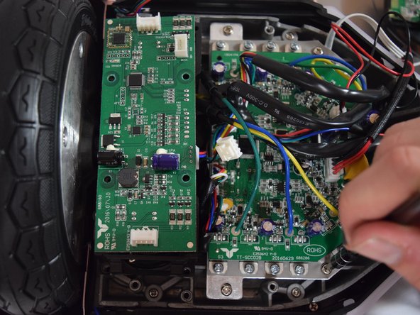
      • Remove the four 11mm Phillips #1 screws that attach the gyroscope board to the mount.

      • Lift the board to reveal the connections on the bottom.

      FixBotに聞いてみる
      コメントを追加

    4. Hover-1 Horizon Left Gyroscope Sensor Board Replacement: 手順 7、 2の画像 1 Hover-1 Horizon Left Gyroscope Sensor Board Replacement: 手順 7、 2の画像 2
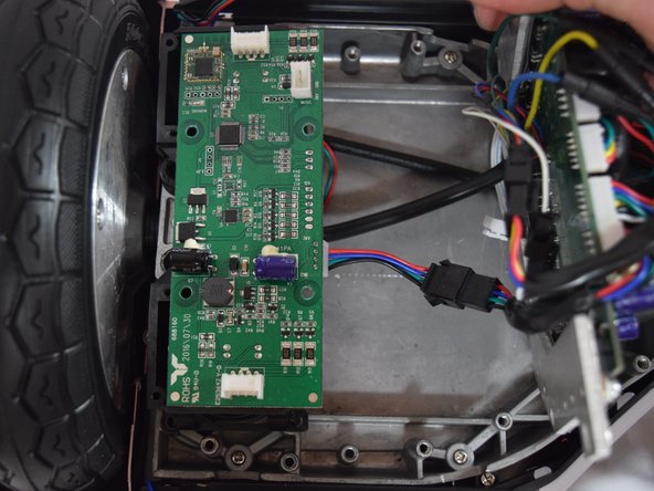
      • Remove the middle connector by squeezing the top of the tab and pulling up.

      FixBotに聞いてみる
      コメントを追加

    5. Hover-1 Horizon Left Gyroscope Sensor Board Replacement: 手順 8、 3の画像 1 Hover-1 Horizon Left Gyroscope Sensor Board Replacement: 手順 8、 3の画像 2 Hover-1 Horizon Left Gyroscope Sensor Board Replacement: 手順 8、 3の画像 3
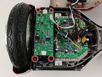
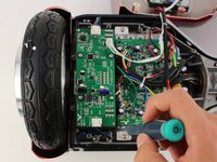
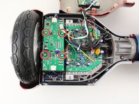
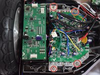
      • Remove the four 12mm Phillips #2 screws that hold the motherboard to the base.

      • Pull the motherboard away from the gyroscope by grabbing it with two hands and pulling it to the right .

      FixBotに聞いてみる
      コメントを追加

    6. Hover-1 Horizon Left Gyroscope Sensor Board Replacement: 手順 9、 3の画像 1 Hover-1 Horizon Left Gyroscope Sensor Board Replacement: 手順 9、 3の画像 2 Hover-1 Horizon Left Gyroscope Sensor Board Replacement: 手順 9、 3の画像 3
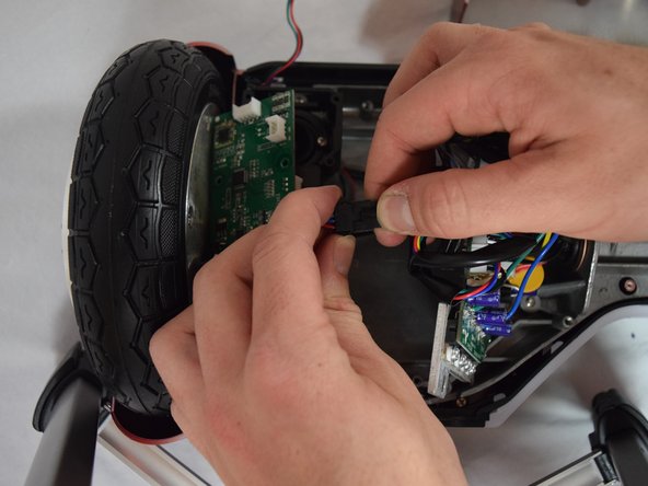
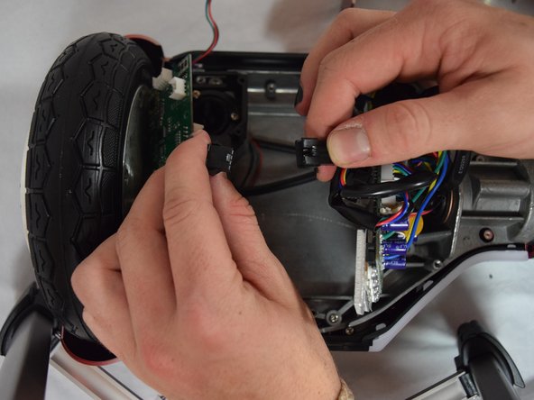
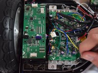
      • Unclip the black connector by squeezing both sides and pulling them apart.

      FixBotに聞いてみる
      コメントを追加

終わりに

To reassemble your device, follow these instructions in reverse order.

キャンセル: このガイドを終了できませんでした。

ある他の人がこのガイドを完成しました。

作成者

4人の作成者と共同で作成されました。

Casey Winans

メンバー登録日: 10/08/18

324 ポイント

2のガイドは作成済み

チーム

Cal Poly, Team S13-G6, White Fall 2018 Cal Poly, Team S13-G6, White Fall 2018人のメンバー

CPSU-WHITE-F18S13G6

4 メンバー

6のガイドは作成済み

0件のガイドコメント

コメントを追加

統計データ:

過去 24時間: 1

過去 7 日: 5

過去 30 日: 30

今までの合計 5,468