メインコンテンツにスキップ
リペアコミュニティに参加 - アカウントの作成

Hover-1 Chrome Left Gyroscope Sensor Board Replacement

必要な工具と部品

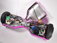
    1. Hover-1 Chrome Left Gyroscope Sensor Board Replacement, Hover-1 Chrome Disassembly: 手順 1、 1の画像 1
      • Flip the Hover-1 Chrome upside down.

      • Use a Phillips #2 screwdriver to remove the fourteen 14 mm screws from the bottom of the Hover-1.

      • Break the two black tape circles, and remove the two 15 mm Phillips screws underneath.

      FixBotに聞いてみる

      コメントを追加

    2. Hover-1 Chrome Left Gyroscope Sensor Board Replacement: 手順 2、 1の画像 1
      • Lift the shell without the speaker grille and unplug the battery.

      FixBotに聞いてみる

      コメントを追加

    3. Hover-1 Chrome Left Gyroscope Sensor Board Replacement: 手順 3、 2の画像 1 Hover-1 Chrome Left Gyroscope Sensor Board Replacement: 手順 3、 2の画像 2
      • Lift the shell with the speaker grille.

      • Unplug the speaker.

      • Unplug the LEDs.

      • Unplug the power button

      • Unplug the charging port.

      FixBotに聞いてみる

      コメントを追加

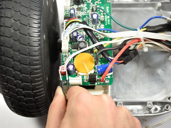
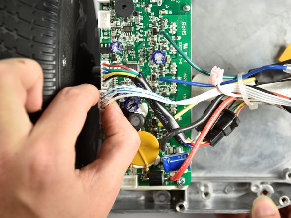
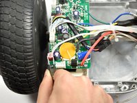
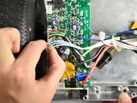
    1. Hover-1 Chrome Left Gyroscope Sensor Board Replacement, Left Gyroscope Sensor Board: 手順 4、 3の画像 1 Hover-1 Chrome Left Gyroscope Sensor Board Replacement, Left Gyroscope Sensor Board: 手順 4、 3の画像 2 Hover-1 Chrome Left Gyroscope Sensor Board Replacement, Left Gyroscope Sensor Board: 手順 4、 3の画像 3
      • Disconnect the speaker cable.

      • Disconnect the cable that travels to the other sensor board.

      FixBotに聞いてみる

      コメントを追加

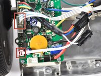
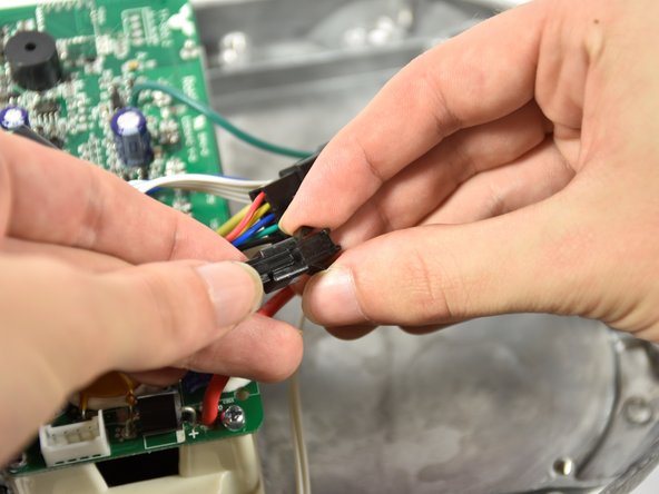
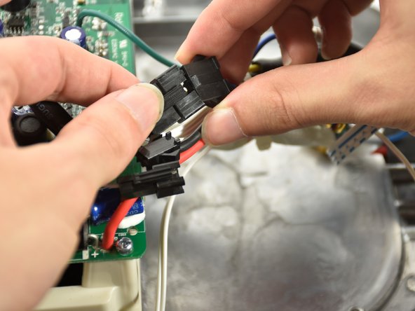
    2. Hover-1 Chrome Left Gyroscope Sensor Board Replacement: 手順 5、 3の画像 1 Hover-1 Chrome Left Gyroscope Sensor Board Replacement: 手順 5、 3の画像 2 Hover-1 Chrome Left Gyroscope Sensor Board Replacement: 手順 5、 3の画像 3
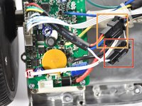
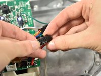
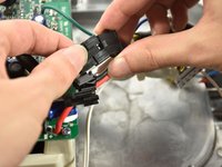
      • Disconnect the smaller connector midway on the cable.

      • Disconnect the larger connector midway on the cable.

      FixBotに聞いてみる

      コメントを追加

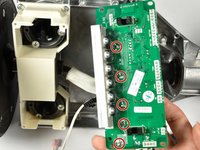
    3. Hover-1 Chrome Left Gyroscope Sensor Board Replacement: 手順 6、 1の画像 1
      • Remove the four 12mm Phillips #2 screws securing the sensor board.

      FixBotに聞いてみる

      コメントを追加

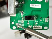
    4. Hover-1 Chrome Left Gyroscope Sensor Board Replacement: 手順 7、 2の画像 1 Hover-1 Chrome Left Gyroscope Sensor Board Replacement: 手順 7、 2の画像 2
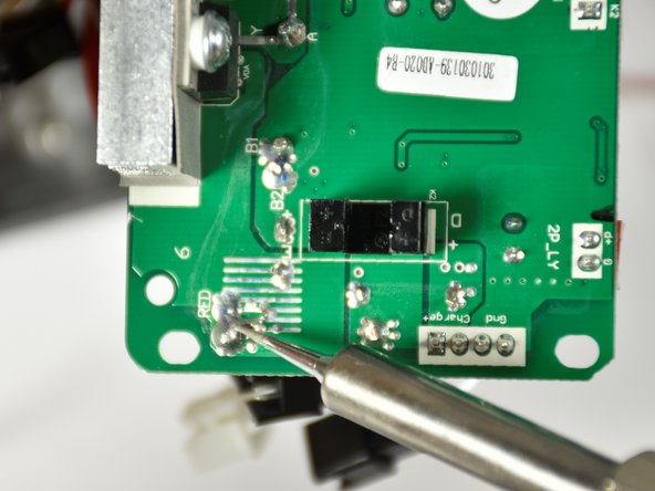
      • Locate the five solder locations on the underside of the gyroscope sensor board.

      • Plug in soldering iron and wait for the tip tip to reach its target temperature.

      • Rest the tip of the iron on the solder and wait for the solder to melt. The wire will drop out of the sensor board.

      • Be aware of where the tip of the soldering iron is at ALL times. Put on safety glasses before picking up the soldering iron. Turn on a fan and face it towards the device to vent harmful fumes away from the solderers face.

      FixBotに聞いてみる

      コメントを追加

終わりに

To reassemble your device, follow these instructions in reverse order.

キャンセル: このガイドを終了できませんでした。

作成者

4人の作成者と共同で作成されました。

Nick McGuire

メンバー登録日: 10/08/18

551 ポイント

4のガイドは作成済み

チーム

Cal Poly, Team S4-G1, White Fall 2018 Cal Poly, Team S4-G1, White Fall 2018人のメンバー

CPSU-WHITE-F18S4G1

4 メンバー

6のガイドは作成済み

0件のガイドコメント

コメントを追加

統計データ:

過去 24時間: 1

過去 7 日: 5

過去 30 日: 30

今までの合計 1,562