メインコンテンツにスキップ

このバージョンは誤った内容を含んでいる可能性があります。最新の承認済みスナップショットに切り替えてください。

必要な工具と部品

  1. この手順は未翻訳です。 翻訳を手伝う。

    : 手順 1、 2の画像 1 : 手順 1、 2の画像 2
    • Insert a SIM card eject tool or a paperclip into the small hole in the SIM card tray, located on the upper left hand side of the phone.

    • Press to eject the tray.

    • This may require a significant amount of force.

  2. この手順は未翻訳です。 翻訳を手伝う。

    : 手順 2、 1の画像 1
    • Remove the SIM card tray assembly from the HTC One M8.

    • When reinserting the SIM card, ensure that it is in the proper orientation relative to the tray.

  3. この手順は未翻訳です。 翻訳を手伝う。

    : 手順 3、 2の画像 1 : 手順 3、 2の画像 2
    • Insert a SIM card eject tool or a paperclip into the small hole in the microSD card tray, located on the upper right hand side of the phone.

    • Press to eject the tray.

    • This may require a significant amount of force.

  4. この手順は未翻訳です。 翻訳を手伝う。

    : 手順 4、 1の画像 1
    • Remove the microSD card tray assembly from the HTC One M8.

    • When reinserting the microSD card, ensure that it is in the proper orientation relative to the tray.

  5. この手順は未翻訳です。 翻訳を手伝う。

    : 手順 5、 2の画像 1 : 手順 5、 2の画像 2
    • Use an iOpener or heat gun to loosen the adhesive on the upper and lower speaker grilles.

    • Refer to the iOpener guide for info on how to use the iOpener.

  6. この手順は未翻訳です。 翻訳を手伝う。

    : 手順 6、 3の画像 1 : 手順 6、 3の画像 2 : 手順 6、 3の画像 3
    • Use a plastic opening tool to gently peel up the lower speaker grille.

    • The adhesive is messy, and can be removed using Goo-gone.

  7. この手順は未翻訳です。 翻訳を手伝う。

    : 手順 7、 2の画像 1 : 手順 7、 2の画像 2
    • Use a plastic opening tool to gently peel up the upper speaker grille.

  8. この手順は未翻訳です。 翻訳を手伝う。

    : 手順 8、 1の画像 1
    • Remove the two silver 3 mm Phillips #00 screws from the top.

    • Remove the four black 4 mm T5 Torx screws from the bottom.

  9. この手順は未翻訳です。 翻訳を手伝う。

    : 手順 9、 3の画像 1 : 手順 9、 3の画像 2 : 手順 9、 3の画像 3
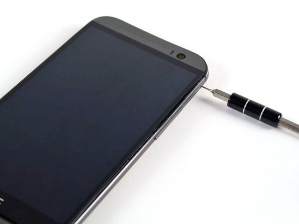
    • Work your way around the perimeter of the phone with a spudger and plastic opening picks to free the clips that secure the rear case to the display assembly.

    • A metal spudger is pictured, but it is best to use a nylon spudger to prevent marring the device.

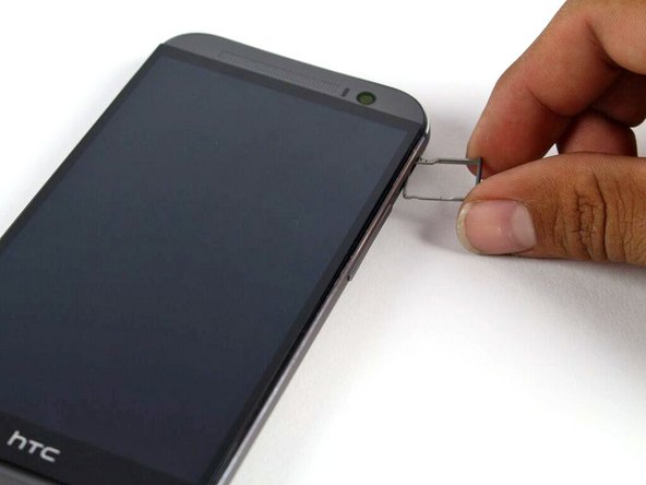
    • Be careful not to lose the power button: it sits loosely in the top of the lower chassis.

    • Significant force may be required to pry the casing apart.

  10. この手順は未翻訳です。 翻訳を手伝う。

    : 手順 10、 2の画像 1 : 手順 10、 2の画像 2
    • Remove the two silver 2 mm Phillips #00 screws securing the battery connector to the motherboard.

    • Use a plastic opening tool to gently pry up the battery connector.

  11. この手順は未翻訳です。 翻訳を手伝う。

    : 手順 11、 3の画像 1 : 手順 11、 3の画像 2 : 手順 11、 3の画像 3
    この手順で使用する道具:
    Tweezers
    $4.99
    購入する
    • Use a spudger to disconnect the two (four) antenna cables.

    • Use the tip of a spudger to disconnect the seven ZIF connectors.

    • Use a pair of tweezers to gently pull the seven ribbon cables free of the connectors.

  12. この手順は未翻訳です。 翻訳を手伝う。

    : 手順 12、 1の画像 1
    • Remove three silver 3mm screws using T5 screwdriver.

  13. この手順は未翻訳です。 翻訳を手伝う。

    : 手順 13、 3の画像 1 : 手順 13、 3の画像 2 : 手順 13、 3の画像 3
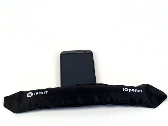
    • Use an iOpener or a heat gun to loosen up the adhesive securing the motherboard to the display assembly.

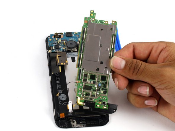
    • Use a plastic opening tool to gently pry the motherboard free of the display assembly.

    • At this point, the bottom speaker is still attached to the motherboard. If you are only replacing the motherboard, refer to the bottom speaker guide to swap your existing speaker to the new motherboard.

ゴール

28 の人々がこのガイドを完成させました。

作成者

6人の作成者と共同で作成されました。

Michael Gonzalez

メンバー登録日: 04/14/15

4,430 ポイント

5のガイドは作成済み

チーム

Cal Poly, Team 5-9, Maness Spring 2015 Cal Poly, Team 5-9, Maness Spring 2015人のメンバー

CPSU-MANESS-S15S5G9

4 メンバー

18のガイドは作成済み

2 件のコメント

Thanks you very much

ngvhiem26 - 返信

all ok. thanks.

Javier - 返信

コメントを追加

統計データ:

過去 24時間: 0

過去 7 日: 6

過去 30 日: 39

今までの合計 25,392